
Electric connector

A technology of electrical connectors and sockets, which is applied in the direction of connection, parts and circuits of connection devices, and can solve problems such as burrs and sharp corner cracks

Pending Publication Date: 2022-05-13
中山得意电子有限公司
View PDF0 Cites 0 Cited by
  • Summary
  • Abstract
  • Description
  • Claims
  • Application Information

AI Technical Summary

Problems solved by technology

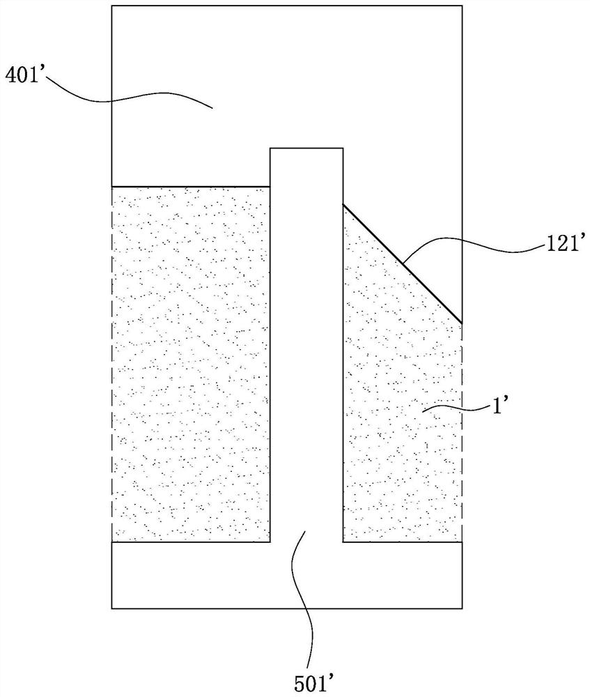
[0004] like figure 1 As shown, the projection of the groove of this electrical connector in the insertion direction coincides with the projection of the opening in the insertion direction, and one end of the opening is directly connected to the guide slope 121 ′, so The insulating body 1' has a sharp corner formed by the terminal groove and the guide slope 121'. During the manufacturing process, molten plastic is injected into the mold cavity of the movable mold and the fixed mold, and the first mold of the fixed mold The mold core 401' and the second mold core 501' of the movable mold are engaged with each other in the groove and the terminal groove so that the molten plastic solidifies to form a sharp corner, and the sharp corner is easy to be injected due to the molten plastic Unsatisfactory and uneven, resulting in burrs, and sharp corners are prone to cracking due to stress concentration

Method used


Image

  • Electric connector
  • Electric connector
  • Electric connector

Examples


Embodiment Construction

[0038] In order to facilitate a better understanding of the purpose, structure, features, and effects of the present invention, the present invention will now be further described in conjunction with the accompanying drawings and specific embodiments.

[0039] Such as Figure 4 to Figure 14As shown, it is an electrical connector 100 of the present invention, which is used to electrically connect a first docking element 200 to a second docking element 300, the first docking element 200 is preferably an electronic card, and the second docking element 300 Preferably a circuit board, the electrical connector 100 includes an insulating body 1, a plurality of terminal assemblies 2 accommodated in the insulating body 1 and a fastener 3; the terminal assembly 2 is used to electrically connect the first A docking element 200 to the second docking element 300 .

[0040] Such as Figure 4 to Figure 14 As shown, the electrical connector 100 defines the longitudinal direction of the insu...


PUM


Abstract

The invention discloses an electric connector, which is characterized in that an insulating body is provided with a plugging groove, a butt joint element is inserted into the plugging groove along the insertion direction, and the insulating body is provided with a side wall at one side of the plugging groove; the side wall is provided with a guide inclined surface, a butt joint surface connected with the guide inclined surface and a plurality of grooves which are concavely arranged from the guide inclined surface and the butt joint surface along the insertion direction, the guide inclined surface is provided with a first boundary connected with the butt joint surface and a second boundary which is arranged at an interval with the first boundary, and the grooves are provided with inner bottom surfaces connected to the guide inclined surface; a terminal groove extends from each groove along the insertion direction, each terminal groove is provided with an opening positioned on the inner bottom surface, the inner bottom surface is provided with a first surface positioned on one side of the opening and two second surfaces positioned on two opposite sides of the opening, the first surface is provided with a first edge connected to the guide inclined surface, the opening is provided with a second edge connected to each second surface, and the first edge and the second edge are arranged along the insertion direction. The first edge is located between the first boundary and the second boundary, and the second edge intersects with an extension line of the first boundary.

Description

【Technical field】 [0001] The invention relates to an electrical connector, in particular to an electrical connector electrically connecting a first docking element and a second docking element. 【Background technique】 [0002] There is an electrical connector in the prior art, which includes an insulating body, and the insulating body is provided with an insertion slot, and the insertion slot is used for inserting a mating element along an insertion direction, and the insulating body is inserted into the insertion slot. One side of one side is provided with a side wall, and the side wall is provided with a guide slope, a butt surface connecting the guide slope, and a plurality of grooves recessed from the butt surface along the insertion direction, from each The groove extends a terminal groove along the insertion direction, the terminal groove has an opening connected to the groove, one end of the opening is directly connected to the guide slope, and the groove is in the ins...

Claims


Application Information

Patent Timeline
IPC IPC(8): H01R12/73H01R13/405H01R13/502
CPCH01R12/73H01R13/405H01R13/502
Inventor 陸元成
Owner 中山得意电子有限公司
Learn More