
Full-suspension revolving door device

A revolving door, full suspension technology, applied in the field of suspension doors, can solve the problems of high rotational inertia, energy loss, low sensitivity, etc., and achieve the effects of no friction loss, long service life, and strong anti-interference ability.

Pending Publication Date: 2022-05-13
WUHAN UNIV OF TECH
View PDF8 Cites 0 Cited by
  • Summary
  • Abstract
  • Description
  • Claims
  • Application Information

AI Technical Summary

Problems solved by technology

[0003] However, at present, the driving mechanism of the revolving door mostly uses indirect transmission devices such as transmission motors and reduction boxes to maintain the door at a relatively constant speed, and there are problems such as low transmission stiffness, high moment of inertia, low sensitivity, and low efficiency; revolving doors Most of the supporting structures use mechanical bearings or circular gear trains to bear the load, the friction between the shafts and the gear trains is large, and the energy loss is serious.

Method used


Image

  • Full-suspension revolving door device
  • Full-suspension revolving door device
  • Full-suspension revolving door device

Examples


Embodiment Construction

[0088] The following will clearly and completely describe the technical solutions in the embodiments of the present invention with reference to the drawings in the embodiments of the present invention.

[0089]In describing the present invention, it should be understood that the terms "center", "longitudinal", "transverse", "upper", "lower", "front", "rear", "left", "right", " The orientations or positional relationships indicated by "vertical", "horizontal", "top", "bottom", "inner" and "outer" are based on the orientations or positional relationships shown in the drawings, and are only for the convenience of describing the present invention and Simplified descriptions, rather than indicating or implying that the device or element referred to must have a particular orientation, be constructed and operate in a particular orientation, and thus should not be construed as limiting the invention. In addition, the terms "first", "second", etc. are used for descriptive purposes only...


PUM


Abstract

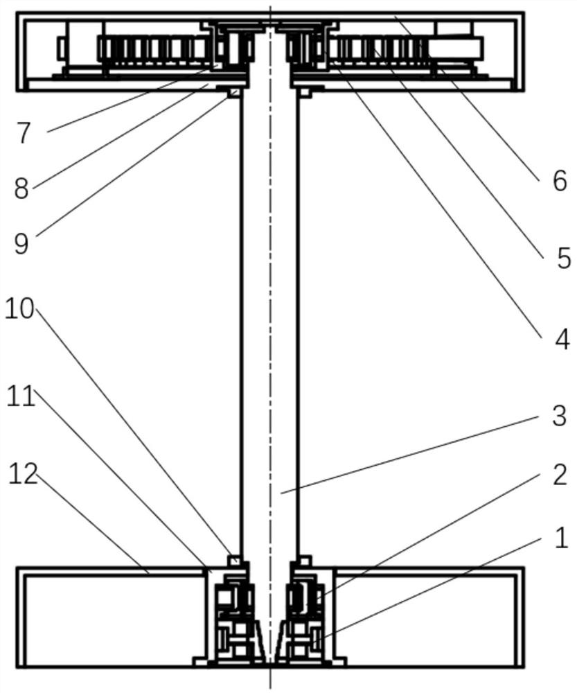
The invention discloses a full-suspension revolving door device which is arranged between an upper wall body and a ground shell cover and comprises an upper bearing shell, a lower bearing shell, a rotating main shaft, a revolving door and an axial magnetic flux motor, the upper bearing shell is arranged in the upper wall body, an upper radial hybrid magnetic suspension bearing is arranged in an upper door frame, and the lower door frame is arranged in the ground shell cover. An axial mixing magnetic suspension bearing and a lower radial mixing magnetic suspension bearing are arranged in the lower portal frame from bottom to top, and a rotating main shaft is arranged in the axial mixing magnetic suspension bearing, the lower radial mixing magnetic suspension bearing and the upper radial mixing magnetic suspension bearing and provided with a rotating disc. The axial magnetic flux motor comprises an axial magnetic flux motor rotor and an axial magnetic flux motor stator, the axial magnetic flux motor rotor is fixed to the rotating disc, the axial magnetic flux motor stator is arranged in the upper wall body, the rotating doors are distributed on the rotating main shaft in a central symmetry mode, full suspension of the whole device in the axial direction is achieved, and the rotating main shaft is controlled to be stable in the radial direction; therefore, the rotation of the rotating main shaft is realized.

Description

technical field [0001] The invention relates to the technical field of floating doors, in particular to a fully suspended revolving door device. Background technique [0002] In modern buildings, the automatic revolving door has become the mainstream of contemporary architectural decoration with its brand-new concept, spacious and open facade and high-style design, and the automatic revolving door has the characteristics of being always open and always closed, which enhances the building quality. The wind-resistant ability of the material reduces the energy consumption of the air conditioner, and can effectively prevent the airflow from bringing odor, sound, and dust into the building, and play the role of isolating the airflow and saving energy. It is widely installed in restaurants, airports, office buildings and commercial buildings. in the entrance and exit system. [0003] However, at present, the driving mechanism of the revolving door mostly uses indirect transmissio...

Claims


Application Information

Patent Timeline
Patent Type & Authority Applications(China)
IPC IPC(8): H02K1/16H02K1/2793H02N15/00F16C32/04E06B3/90
CPCH02K1/16H02K1/2793H02N15/00F16C32/0406E06B3/90
Inventor 吴华春陈卓郑凡卓胡光金
Owner WUHAN UNIV OF TECH
Learn More