Desk capable of being overturned downwards

A technology for flipping tables and tables, which is applied in the field of office equipment and smart furniture. It can solve the problems that the flipping gap cannot be well eliminated, the stability of the folding table is not high, and the flipping grip is not in place, so as to improve the overall aesthetics, Ease of assembly and improved safety

Active Publication Date: 2022-05-17
CHANGZHOU KAIDI ELECTRICAL INC
View PDF5 Cites 0 Cited by
  • Summary
  • Abstract
  • Description
  • Claims
  • Application Information

AI Technical Summary

Problems solved by technology

The stability of the folding table is not high, it is only used for a short time
However, in the existing flip tables on the market, there will be gaps between the tabletops, but at present such flip gaps cannot be eliminated well, and there is a risk of flipping and pinching hands or other objects that will cause the flipping to fail.

Method used


Image

  • Desk capable of being overturned downwards
  • Desk capable of being overturned downwards
  • Desk capable of being overturned downwards

Examples


Embodiment 1

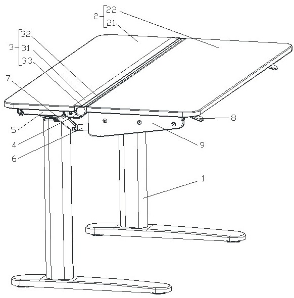
[0048] Such as figure 1 As shown, a table that can be turned down includes a table leg assembly 1 and a table board assembly 2. The table leg assembly 1 is a lifting table leg, and the table board assembly 2 is composed of a fixed table board 21 and a reversible table board 22. The fixed table board 21 is fixed on the table leg assembly 1, and the flip table 22 is rotatably connected to one side edge of the fixed table 21, the rotation angle of the flip table 22 is -130°~0°, the fixed table 21 and the flip table 22 The connection is provided with a connection assembly 3 that always covers the connection during the reversing stroke of the reversing table 22. The connection assembly 3 includes a fixed profile 31 fixed on the fixed table 21 and a flipper connected to the reversing table 22 to follow its action. The profile 32 has an overlapping joint with the fixed profile 31 during the action of turning over the profile 32 .

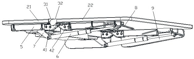
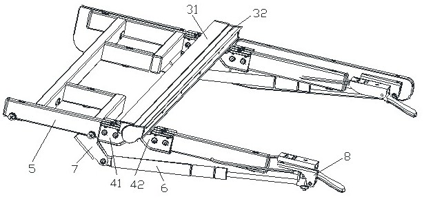
[0049] Such as figure 2 with image 3As shown, a...

Embodiment 2

[0056] The difference with Embodiment 1 is: as Figure 9 As shown, the two ends of the vertical section 311 of the fixed profile 31 extend horizontally to form a flange 314 enclosing the end of the fixed table 21, and the horizontal section 312 is formed by extending the flange 314 at the upper end of the vertical section 311 in the opposite direction. Such as Figure 10 As shown, the two ends of the vertical connecting portion 321 of the turning profile 32 respectively extend horizontally to form a connecting flange 325 enclosing the end of the turning table 22 , and the connecting flange 325 is connected to the horizontal transition portion 322 through a slope 326 .

[0057] The flange 314 and the connecting flange 325 are not only convenient for the connection and installation of the fixed profile 31 and the overturned profile 32, but also ensure that the joint will not be worn by external force.

Embodiment 3

[0059] The difference with Embodiment 2 is that: as Figure 11 As shown, a supporting member 10 is provided on the inner side of the turning profile 32 , and the upper surface profile of the supporting member 10 matches the inner wall profile of the turning profile 32 . The inner end of the support member 10 is provided with a barb portion 101 , and the end of the arc-shaped extension portion 323 is provided with an engaging section 3231 matched with the barb portion 101 . Specifically, such as Figure 12 As shown, a 7-shaped notch 102 is provided on the inner side of the support member 10, and a reverse 7-shaped barb 101 is formed at the bottom of the 7-shaped notch 102. The barb 101 and the notch 102 form an upper left end. In the receiving part of the opening, the clamping section 3231 has a stepped structure, which is limited by the opening after entering the receiving part through the opening.

[0060] The support member 10 can be placed at any position as required to p...


PUM


Abstract

The table comprises a table leg assembly and a table plate assembly, the table plate assembly is composed of a fixed table plate and a turnover table plate, the fixed table plate is fixed to the table leg assembly, the turnover table plate is rotationally connected to the edge of one side of the fixed table plate, the rotation angle of the turnover table plate ranges from-130 degrees to 0 degree, and the turnover table plate is fixed to the table leg assembly. A connecting assembly which always covers the connecting position within the overturning stroke of the overturning table plate is arranged at the connecting position of the fixed table plate and the overturning table plate, and the connecting assembly comprises a fixed profile fixed to the fixed table plate and an overturning profile which is connected to the overturning table plate and moves along with the overturning table plate. And a lap joint is formed between the fixing section bar and the fixing section bar all the time. According to the table capable of being overturned downwards, complete clamping prevention in the overturning process is achieved, and safety is improved; the gap problem occurring in the overturning process is eliminated, and the overall attractiveness is improved; the hinge is overturned and limited to ensure that the overturning angle meets the requirement; the overturning structure is simple, and assembling is easy.

Description

technical field [0001] The invention relates to the fields of intelligent furniture and office equipment, in particular to a table that can be turned down. Background technique [0002] A traditional table has a flat plate and supports underneath, and can be used for eating, writing or working. At present, whether it is a family or a workplace, more and more attention is paid to the utilization of space, so some folding tables or flip tables have appeared. The stability of the folding table is not high, and it is only used for a short time. However, for the reversing tables on the existing market, there will be gaps between the desktops, but such a reversing gap cannot be well eliminated at present, and there is a risk of flipping and pinching hands or clamping other objects to cause the situation that the flipping is not in place. Contents of the invention [0003] The technical problem to be solved by the present invention is: to overcome the deficiencies in the prior ...

Claims


Application Information

Patent Timeline
Patent Type & Authority Applications(China)
IPC IPC(8): A47B13/08A47B3/00
CPCA47B13/081A47B3/00
Inventor 胡鸣涛殷红兵陈垚为张松松
Owner CHANGZHOU KAIDI ELECTRICAL INC
Why Eureka
Try Eureka