
Signal lamp lens

A signal lamp and lens technology, applied in the field of signal lamps, can solve the problems of complex optical structure, high cost, low light efficiency of signal lamp lenses, etc., and achieve the effects of reducing complexity, being easy to clean, and being convenient for processing and manufacturing.

Pending Publication Date: 2022-05-17
上海康耐司信号设备有限公司
View PDF0 Cites 0 Cited by
  • Summary
  • Abstract
  • Description
  • Claims
  • Application Information

AI Technical Summary

Problems solved by technology

[0002] At present, most of the vehicle signal lights on the market are designed by the optical structure of the light source, condenser lens and light distribution lens. Usually, at least two lenses are needed to achieve the light distribution effect. The existing signal light lenses have low light efficiency and low optical structure. complex and costly

Method used

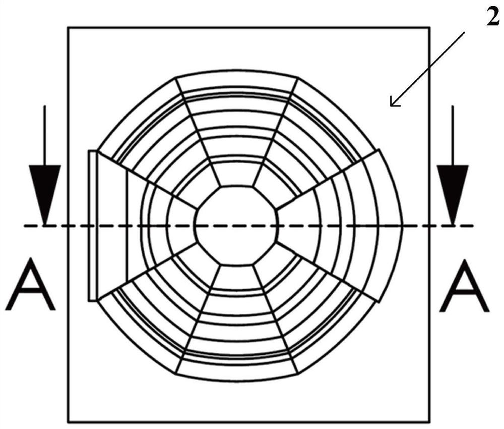
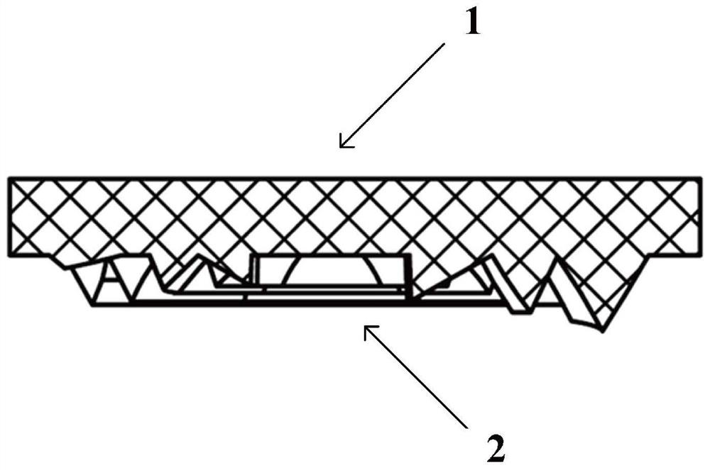
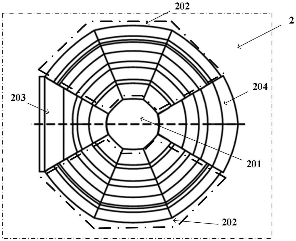

Image

  • Signal lamp lens
  • Signal lamp lens
  • Signal lamp lens

Examples


Embodiment Construction

[0046] The following will clearly and completely describe the technical solutions in the embodiments of the present invention with reference to the accompanying drawings in the embodiments of the present invention. Obviously, the described embodiments are only some, not all, embodiments of the present invention. Based on the embodiments of the present invention, all other embodiments obtained by persons of ordinary skill in the art without creative efforts fall within the protection scope of the present invention.

[0047] It should be noted that, in the case of no conflict, the embodiments of the present invention and the features in the embodiments can be combined with each other.

[0048] The present invention will be further described below in conjunction with the accompanying drawings and specific embodiments, but not as a limitation of the present invention.

[0049] In a preferred embodiment of the present invention, as Figure 1 to Figure 3 As shown, a signal light le...


PUM


Abstract

The invention relates to the technical field of vehicle signal lamps, in particular to a vehicle signal lamp lens. The vehicle signal lamp lens comprises a lens outer surface which is a smooth surface; the lens inner surface comprises a polygonal lens and a fan-shaped lens group; the polygonal lens is positioned in the central area of the inner surface of the lens; the central point of the fan-shaped lens group coincides with the central point of the polygonal lens, and the fan-shaped lens group is spliced with each side of the polygonal lens; and the fan-shaped lens group comprises a plurality of insections with different radians. The outer surface of the lens is a smooth surface which is convenient to process and manufacture and easy to clean; different insections are arranged on the inner surface of the lens according to a certain rule to form a fan-shaped lens group, so that the design complexity is reduced, and a mold is convenient to process and manufacture. Due to the fact that the angle on each insection is precisely designed, precise control over light emitted by the light source is achieved, and the utilization efficiency of the light is also improved.

Description

technical field [0001] The invention relates to the technical field of signal lamps, in particular to a signal lamp lens. Background technique [0002] At present, most of the vehicle signal lights on the market are designed by the optical structure of the light source, condenser lens and light distribution lens. Usually, at least two lenses are needed to achieve the light distribution effect. The existing signal light lenses have low light efficiency and low optical structure. Complicated and costly. [0003] Therefore, a new signal light lens needs to be proposed to solve the above problems. Contents of the invention [0004] The purpose of the present invention is to provide a vehicle signal lamp that only needs one lens and an optical structure on the inner surface of the lens to meet the light intensity requirements of the vehicle signal lamp regulations. [0005] In order to achieve the above object, the present invention proposes a signal light lens for vehicle li...

Claims


Application Information

Patent Timeline
Patent Type & Authority Applications(China)
IPC IPC(8): F21S43/20F21V5/00F21V5/04F21W103/00F21W107/10
CPCF21S43/26F21V5/007F21V5/045F21W2103/00F21W2107/10
Inventor 程遥飞潘方亮
Owner 上海康耐司信号设备有限公司
Learn More