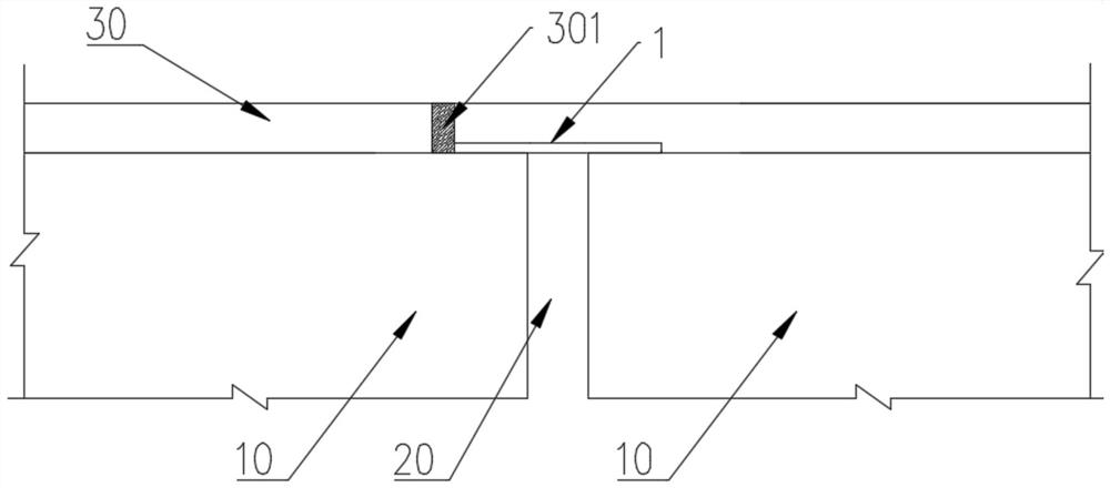
Simple foot bridge expansion joint structure

A technology for pedestrian bridges and expansion joints, applied in bridges, bridge construction, bridge parts, etc., can solve the problems of troublesome construction, poor landscape, obvious segmentation, etc., and achieve the effect of good landscape effect, simple construction and continuous color.

Pending Publication Date: 2022-05-20
中国市政工程西南设计研究总院有限公司
View PDF0 Cites 0 Cited by
  • Summary
  • Abstract
  • Description
  • Claims
  • Application Information

AI Technical Summary

Problems solved by technology

This method can adapt to beam end deformation and various structural joint widths, but the strength of the filler is not enough. When the structural joints are wide, there will be a certain width of low-strength pavement, which is easy to damage and affects practicality.
[0004] 2. The pavement layer is disconnected, the upper cover is made of steel plates, and the two ends of the structural joints are respectively equipped with a fixed end and a sliding end of the steel plate; this scheme can ensure that the pavement layer has continuous strength and is not easy to be damaged, but due to the large difference between the steel plate material and the pavement layer, There are relatively obvious segments, which affect the landscape effect;
[0005] 3. Flat steel plates are laid on the structural joints, and the pavement layer at the end of the steel plates is simply cut; this scheme has little impact on the landscape effect, but it cannot fully adapt to the longitudinal displacement of the beam end, and the cut joints are easily damaged when the temperature rises
[0006] 4. Adopt the commonly used section steel expansion joints for the roadway; the durability is good, the pavement layer is discontinuous, the landscape is poor, and the construction is troublesome, so it is not suitable for pedestrian bridges

Method used


Image

  • Simple foot bridge expansion joint structure

Examples


Embodiment Construction

[0023] In the present invention, unless otherwise clearly specified and limited, terms such as "installation", "connection", "connection" and "fixation" should be understood in a broad sense, for example, it can be a fixed connection or a detachable connection , or integrated; it can be directly connected or indirectly connected through an intermediary, it can be the internal communication of two elements or the interaction relationship between two elements. The "first", "second" and similar words mentioned in this application do not indicate any order, quantity or importance, but are only used to distinguish different components. Likewise, words like "a" or "one" do not denote a limitation in number, but indicate that there is at least one. In the implementation of this application, "and / or" describes the association relationship of associated objects, indicating that there may be three types of relationships, for example, A and / or B, which may mean: A exists alone, A and B e...


PUM


Abstract

The invention relates to the technical field of pedestrian bridge expansion joints, and particularly discloses a simple pedestrian bridge expansion joint structure which comprises a caulking formed in a pavement layer, a structural joint located between two adjacent span main beams and a steel cover plate installed on a main beam structure and located above the structural joint. The caulking joint is located above one span of main beam structure, and the structural joint and the caulking joint are arranged in a staggered mode. The device can adapt to temperature change, so that the main beam structure and the pavement structure can realize telescopic deformation.

Description

technical field [0001] The invention relates to the technical field of bridge expansion joints, and more specifically, relates to a simple footbridge expansion joint structure. Background technique [0002] In the prior art, the processing methods for expansion joints specifically include the following methods: [0003] 1. Set up U-shaped or V-shaped or W-shaped metal plates at structural joints, and fill the metal plates with fillers such as sealant or asphalt lint, which can adapt to the longitudinal deformation of the beam end through the deformation of U-shaped or V-shaped or W-shaped metal plates. This method can adapt to beam end deformation and various structural joint widths, but the strength of the filler is not enough. When the structural joints are wide, there will be a low-strength pavement layer of a certain width, which is easily damaged and affects practicability. [0004] 2. The pavement layer is disconnected, the upper cover is made of steel plates, and the...

Claims


Application Information

Patent Timeline
IPC IPC(8): E01D19/06E01D1/00
CPCE01D19/065E01D1/00
Inventor 董东坡高飞李佳王志华马新宇黄军冯兴吕会龙
Owner 中国市政工程西南设计研究总院有限公司
Why Eureka
Try Eureka