Large underground engineering cavern construction ventilation structure and construction method thereof

A technology for underground engineering and caverns, applied in underground chambers, separation methods, chemical instruments and methods, etc., can solve problems such as poor ventilation effects, achieve the effects of maintaining dust-proof effects, improving poor ventilation effects, and strong practicability

Active Publication Date: 2022-05-24
河南新华五岳抽水蓄能发电有限公司 +1
View PDF11 Cites 3 Cited by
  • Summary
  • Abstract
  • Description
  • Claims
  • Application Information

AI Technical Summary

Problems solved by technology

[0004] The purpose of the present invention is to provide a large-scale underground engineering cavern construction ventilation structure and its construction method in order to solve the above problems. A periodically rotating exhaust pipe is arranged at the air outlet end of the fan, and the exhaust pipe that automatically changes direction is used as The air outlet port of the fan helps to uniformly ventilate the interior area of ​​the large-sized cave, thereby improving the problem of poor ventilation in the existing underground caverns, and setting a filter plate at the air inlet end of the air cylinder and automatically cleaning the filter plate Clean the components to maintain the dust-proof effect of the internal rotating parts of the fan, and avoid the dust problem in the underground cavern from affecting the normal use of the ventilation equipment. It is practical, see the details below

Method used


Image

  • Large underground engineering cavern construction ventilation structure and construction method thereof
  • Large underground engineering cavern construction ventilation structure and construction method thereof
  • Large underground engineering cavern construction ventilation structure and construction method thereof

Examples


Embodiment Construction

[0033]In order to make the objectives, technical solutions and advantages of the present invention clearer, the technical solutions of the present invention will be described in detail below. Obviously, the described embodiments are only some, but not all, embodiments of the present invention. Based on the embodiments of the present invention, all other implementations obtained by those of ordinary skill in the art without creative work fall within the protection scope of the present invention.

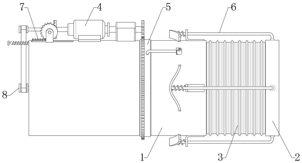
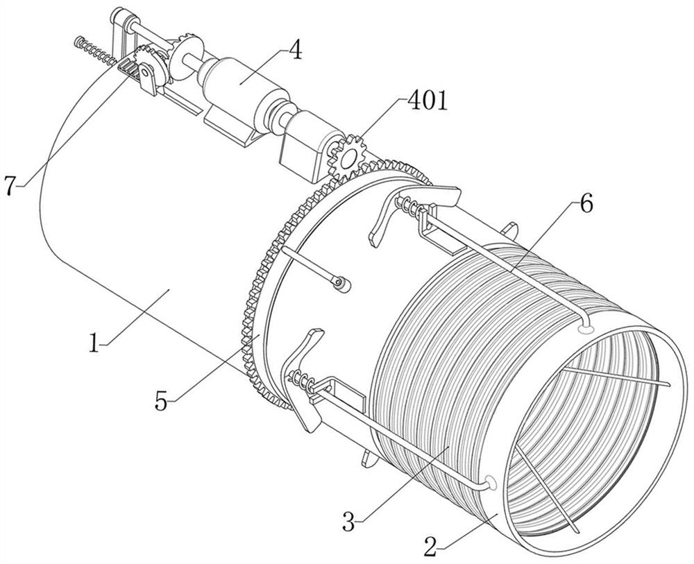
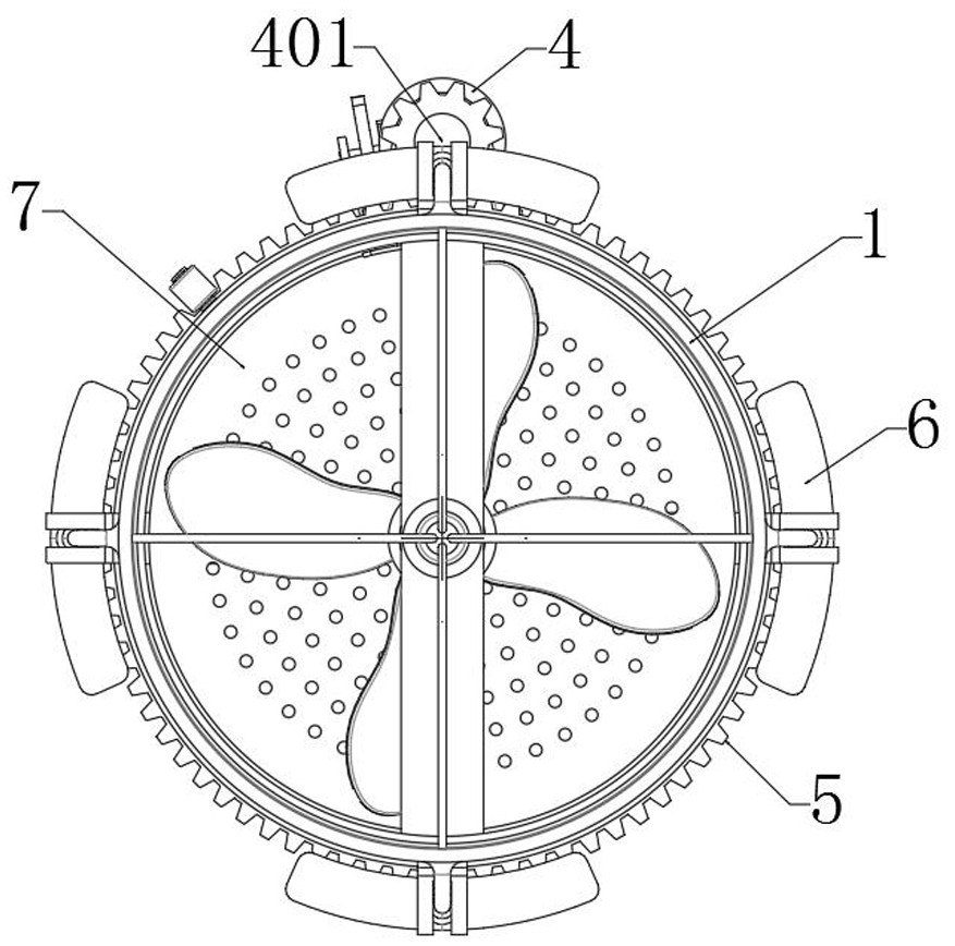
[0034] see Figure 1-Figure 7 As shown, the present invention provides a large-scale underground engineering cavern construction ventilation structure, including an air duct 1 and an exhaust pipe 2, the exhaust duct 2 is arranged on the outside of the end of the air duct 1, and the exhaust duct 2 and the air duct 1 are connected. A corrugated cover 3 is communicated between, and the corrugated cover 3 is made of flexible material to ensure that when the exhaust duct 2 adjusts the air...


PUM


Abstract

The invention discloses a large underground engineering cavern construction ventilation structure which comprises an air duct and an exhaust pipe, the exhaust pipe is arranged on the outer side of the end of the air duct, a corrugated cover is communicated between the exhaust pipe and the air duct, an auxiliary ring is rotationally matched with the outer portion of the air duct, and the auxiliary ring is arranged on the outer side of the air duct. And a double-shaft motor for driving the auxiliary ring to rotate is fixed on the top side of the air duct. The device has the beneficial effects that the exhaust pipe rotating periodically is arranged at the air outlet end of the fan, the double-shaft motor for driving the fan to rotate is used for synchronously driving the auxiliary ring to rotate, and then the push rod and the guide wheel on the outer side of the auxiliary ring are used for sequentially pushing the pressing plates on the multiple sets of limiting rods to move; the angle adjusting process of the exhaust pipe is achieved under the pushing effect of the limiting rod, the exhaust pipe with the direction automatically changed serves as an air outlet end opening of the draught fan, then uniform ventilation can be conducted on the inner area of a large-size cavern, and the problem that the ventilation effect is poor due to the fact that the space size of an existing underground cavern is large is solved.

Description

technical field [0001] The invention belongs to the technical field of underground engineering equipment, and in particular relates to a large-scale underground engineering cavern construction ventilation structure and a construction method. Background technique [0002] The ventilation problem during the construction of large-scale underground caverns such as underground powerhouses in hydropower projects is a very complex problem. At present, there are not many studies on this aspect at home and abroad, and there is basically no mature design and calculation theory, and mature experience that can be used for reference. In construction, due to improper ventilation structure design, unnecessary investment is added to the construction or poor ventilation effect, and the construction air environment is bad, which seriously restricts the progress of the project. Underground engineering refers to the construction of underground space resources deep below the ground It includes u...

Claims


Application Information

Patent Timeline
Patent Type & Authority Applications(China)
IPC IPC(8): E21F1/00E21F1/04E21F1/06E21F1/08F04D25/08B01D46/10B01D46/681B01D46/48E21D13/04
CPCE21F1/00E21F1/04E21F1/06E21F1/08F04D25/08B01D46/10B01D46/48E21D13/00Y02E10/20
Inventor 王竹波张帆张旭潘军伟杨明涛于刚周廷江崔帅帅陈凡
Owner 河南新华五岳抽水蓄能发电有限公司
Why Eureka
Try Eureka