Anti-floating anchor rod detection device and detection method for underground space
A technology for anti-floating anchor rods and underground spaces, which is applied to measuring devices, applying stable tension/pressure to test the strength of materials, instruments, etc., and can solve problems that affect the use of the device, insufficient compressive strength of the device, and difficult installation and operation. , to achieve the effect of reducing installation steps, reducing manual operation intensity and increasing support pressure
- Summary
- Abstract
- Description
- Claims
- Application Information
AI Technical Summary
Problems solved by technology
Method used
Image
Examples
Embodiment 1
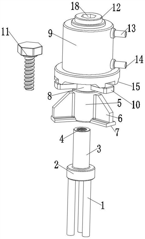
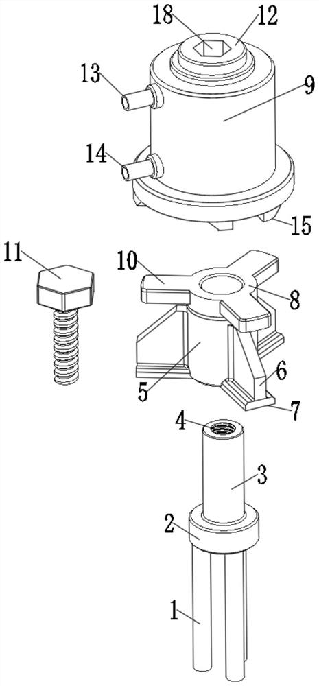
[0033] Floating anchors need to be tested for their pressure before use. The existing anti-floating anchors are usually composed of three reinforcing bars. see Figure 1-6 , and discloses an anti-floating anchor rod detection device and a detection method for underground space, wherein the anti-floating anchor rod detection device for underground space includes a lower end connecting seat 2 and a floating rod main body 1 at the lower end of the lower end connecting seat 2, and the lower end connecting seat 2. The upper end is provided with a fixed shaft 3, the top of the fixed shaft 3 is provided with a fixed inner notch 4, the upper end of the fixed shaft 3 is installed with a matching shaft sleeve 8, the interior of the matching shaft sleeve 8 is provided with a through groove 27, and the upper end of the matching shaft sleeve 8 is provided. A hydraulic cylinder 9 is installed, a hydraulic pressure chamber 19 is arranged inside the hydraulic cylinder 9, a driving inner shaft...
Embodiment 2
[0036] The pulling of the product by the detection device will lead to insufficient supporting strength, and a supporting structure is required. This embodiment is an improvement made on the basis of Embodiment 1. For details, please refer to Figure 1-6 , a fixed seat 5 is installed on the upper end of the fixed shaft 3 .
[0037] Place the fixing base 5 on the upper end of the ground, and pass the fixing shaft 3 through the through groove 27 of the fixing base 5. At this time, one end of the fixing bolt 11 can be inserted from the upper end of the fixing base 5, and the fixing bolt 11 can be screwed into the thread. and the upper end diameter of the fixing bolt 11 is larger than the inner diameter of the through groove 27, so that the pressure of the fixing bolt acts on the inner side of the fixing seat 5, and forms a fixing effect on the fixing shaft 3, and improves the supporting effect between the fixing shaft 3 and the ground.
Embodiment 3
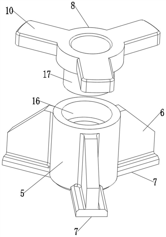
[0039] The structural strength of the fixed seat 5 is not enough, and it is difficult to support a large weight. This embodiment is an improvement made on the basis of Embodiment 2. For details, please refer to Figure 1-6 The outer side of the fixed seat 5 is provided with a reinforcing rib plate 6 , and the lower end of the reinforcing rib plate 6 is provided with a fitting base 7 .
[0040] When the floating rod main body 1 exerts the pressure on the outside of the fixed seat 5 through the fixing bolt 11 , the fixed seat 5 will disperse the pressure at the reinforcing rib plate 6 and press down on the fitting base 7 through the downward pressing of the reinforcing rib plate 6 force, and the fitting base 7 is perpendicular to the reinforcing rib plate 6, and is completely in contact with the ground, effectively dispersing the force of the reinforcing rib plate 6 pressing down, expanding the bearing area of the fitting base 7, thereby improving, The supporting area of the...
PUM
 Abstract
Description
Claims
Application Information
 - R&D Engineer
- R&D Manager
- IP Professional
- Industry Leading Data Capabilities
- Powerful AI technology
- Patent DNA Extraction
Browse by: Latest US Patents, China's latest patents, Technical Efficacy Thesaurus, Application Domain, Technology Topic, Popular Technical Reports.
© 2024 PatSnap. All rights reserved.Legal|Privacy policy|Modern Slavery Act Transparency Statement|Sitemap|About US| Contact US: help@patsnap.com


