Light measuring device

A light measurement and light spot technology, applied in the direction of measuring devices, optics, optical components, etc., can solve the problems of high price and low light receiving efficiency

Pending Publication Date: 2022-05-24
USHIO (SUZHOU) CO LTD
View PDF0 Cites 0 Cited by
  • Summary
  • Abstract
  • Description
  • Claims
  • Application Information

AI Technical Summary

Problems solved by technology

Therefore, no matter how the light-receiving elements are arranged, the problem that light is irradiated to the area other than the light-receiving part cannot be avoided, and there is a problem of low light-receiving efficiency.
[0005]

Method used


Image

  • Light measuring device
  • Light measuring device
  • Light measuring device

Examples


Embodiment Construction

[0028] Hereinafter, the optical measuring device of the present invention will be described in detail with reference to the accompanying drawings.

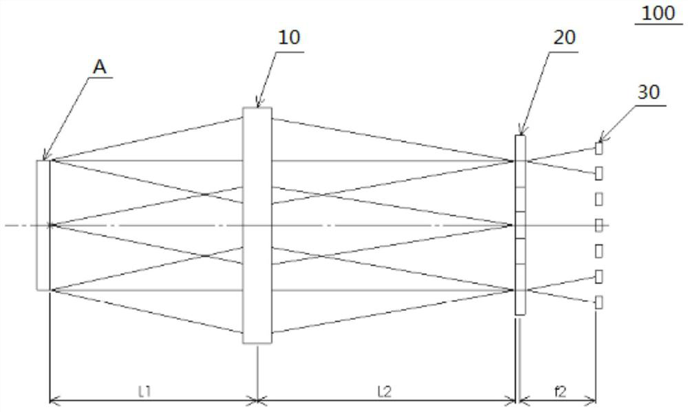
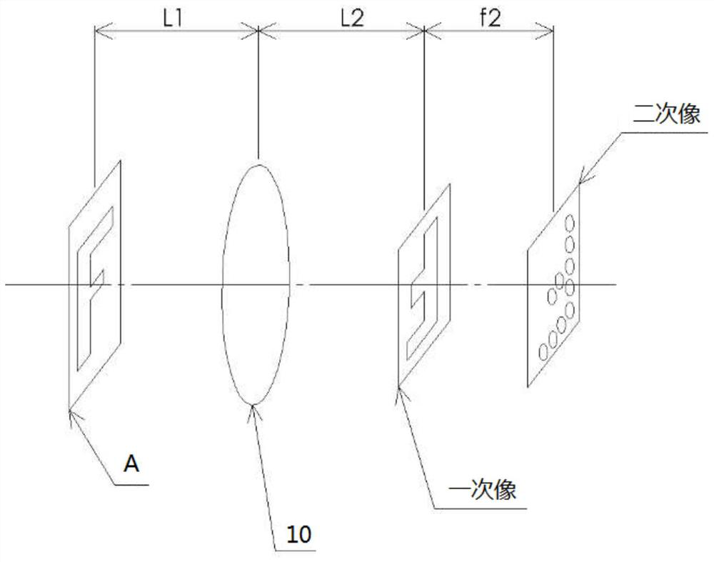
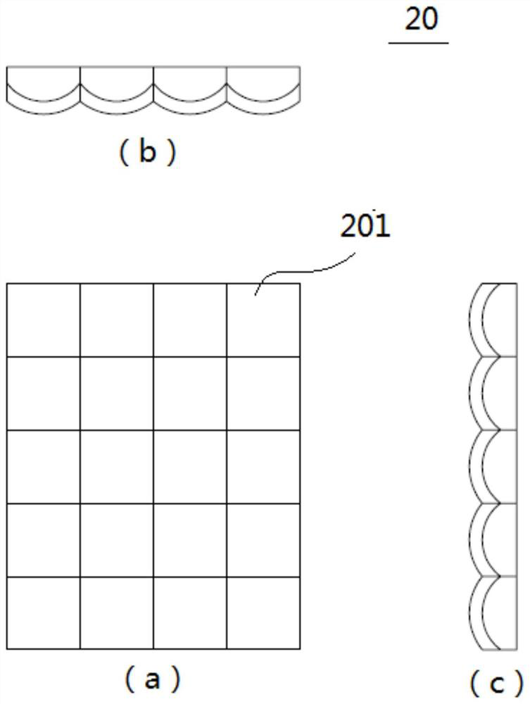
[0029] The optical measurement device 100 according to the embodiment of the present invention will be described based on the drawings. figure 1 It is a schematic diagram which shows the whole of the optical measurement apparatus which concerns on embodiment of this invention. figure 2 It is a schematic diagram showing the formation of a primary image on the discrete lens array and the formation of a secondary image on the light-receiving element array. image 3 is a schematic diagram showing a lens array for discrete use, in which, image 3 (a) is a front view viewed from the traveling direction of the light, image 3 (b) is a top view from above, image 3 (c) is a side view viewed from the side. Figure 4 It is a schematic diagram showing the light-receiving element array.

[0030] The light measuring device 100 measures t...


PUM


Abstract

A light measurement device for measuring light from an observation object, the light measurement device being characterized by being provided with: an imaging lens for transmitting the light and forming a primary image; and a lens array for dispersion, which is disposed downstream of the imaging lens in the direction of travel of the light, and which is formed by arranging a plurality of lenses for dispersion in an array, and which disperses the light having formed the primary image into a plurality of spots after passing through each of the lenses for dispersion. And converting the primary image into a secondary image formed by the plurality of discrete light spots. And a light-receiving element array which is disposed downstream of the discrete lens array in the direction of travel of light and in which a plurality of light-receiving elements are disposed in an array corresponding to the discrete lens array, and in which each of the discrete light spots is received by a light-receiving unit of each of the light-receiving elements.

Description

technical field [0001] The present invention relates to a light measuring device for measuring light. Background technique [0002] Conventionally, there are optical measurement devices that measure light from an observation object. These include high-sensitivity cameras. However, the price of such a high-sensitivity camera increases according to the increase in sensitivity, and there is a problem that the cost increases. [0003] In order to keep costs down, it has been proposed to employ a light-receiving element that can realize high sensitivity at a low price, and that the light-receiving element is composed of a photodiode, a photomultiplier tube, and the like. However, when one light-receiving element is used, there is a problem in that it is impossible to measure light having a two-dimensional distribution. [0004] In order to measure two-dimensionally distributed light, there has been proposed a two-dimensional distribution of a plurality of light-receiving eleme...

Claims


Application Information

Patent Timeline
IPC IPC(8): G01N21/17G01N21/01G02B27/09
CPCG01N21/17G01N21/01G02B27/0927G02B27/0961G01N2021/0112
Inventor 越石直孝大河内健吾
Owner USHIO (SUZHOU) CO LTD
Why Eureka
Try Eureka