Storage type emergency power supply with shockproof protection function
A technology for shock-proof protection and emergency power supply, applied in circuits, current collectors, electric vehicles, etc., can solve the problems of emergency power supply damage, lack of shock-proof devices, and inability to provide
- Summary
- Abstract
- Description
- Claims
- Application Information
AI Technical Summary
Problems solved by technology
Method used
Image

Examples
Embodiment 1
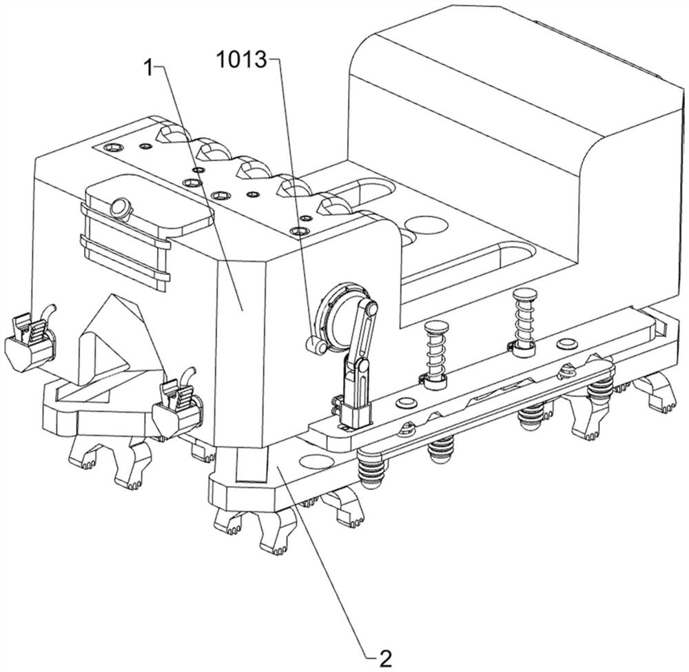
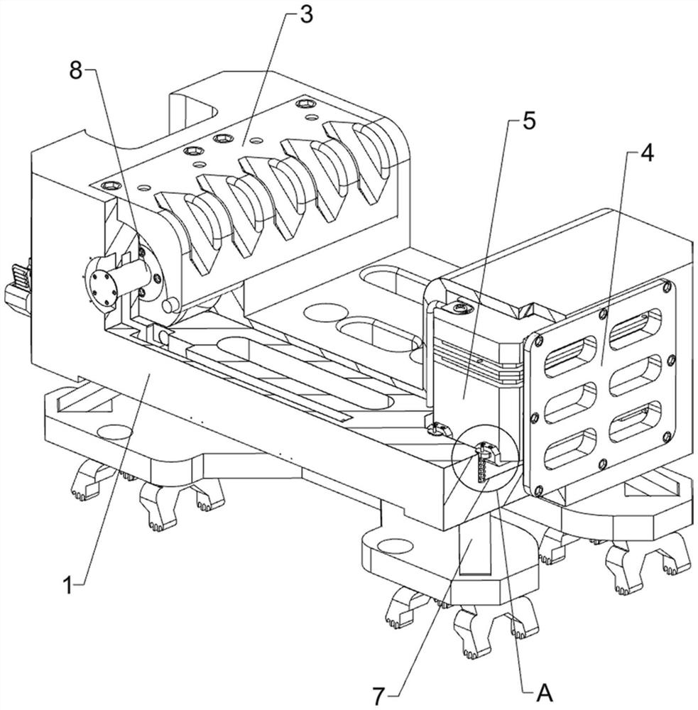
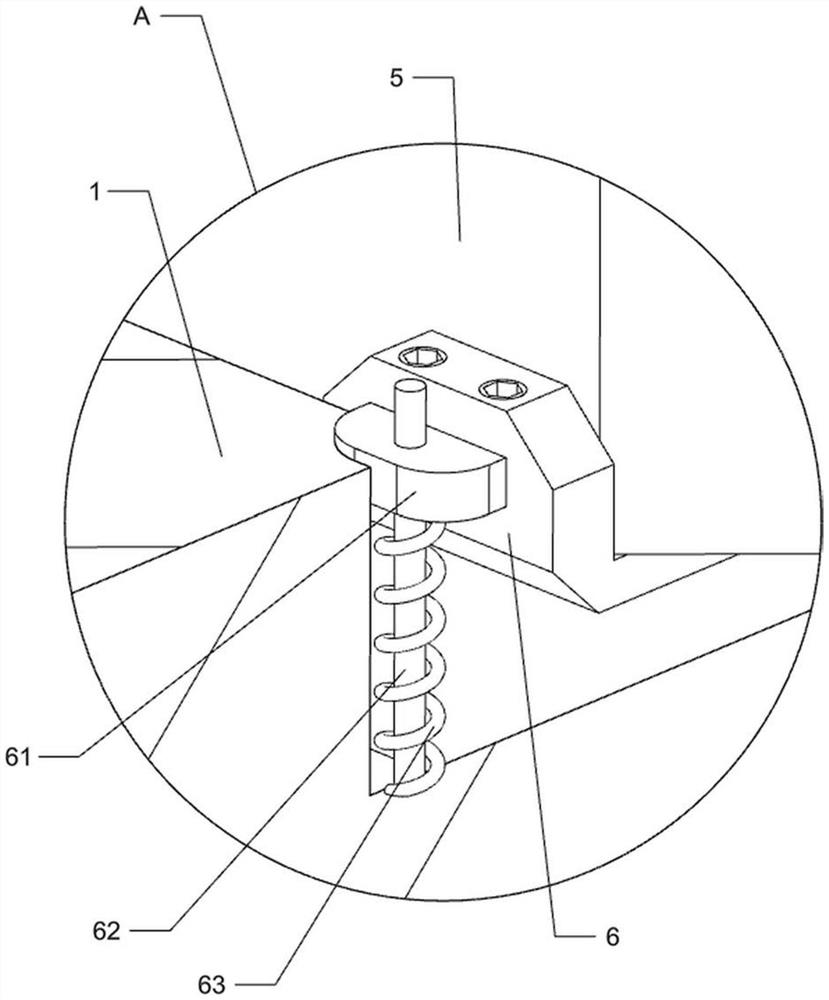
[0040] A retractable emergency power supply with shock protection function, such as Figure 1-Figure 7 As shown, it includes placing bottom box 1, placing bottom plate 2, sealing cover 3, protective bottom plate 4, battery 5, shock-absorbing chassis 6, positioning bottom block 61, positioning guide post 62, positioning spring 63, shock-absorbing mechanism 7 and The power connection mechanism 8, the middle of the bottom box 1 is slidably provided with the bottom plate 2, the bottom of the bottom box is fixed with four rubber pads at intervals, and the upper left part of the bottom box 1 is hingedly provided with a sealing cover 3, and the bottom box 1 is placed The right part is connected with the protective bottom plate 4 by means of bolts, and four positioning guide posts 62 are fixedly connected to the lower side of the right part of the bottom box 1 at intervals. The positioning guide post 62 is slidably provided with a positioning bottom block 61 , and the positioning guide...
Embodiment 2
[0045] On the basis of Example 1, as Figure 8-Figure 10 As shown, it also includes a reset mechanism 9. The reset mechanism 9 includes a positioning gear 91, a reduction gear 92, a reversing short column 93, a positioning belt assembly 94, a positioning plate 95, a first reset guide post 96 and a first reset spring 97 , a positioning gear 91 is fixed to the outside of the fixed horizontal shaft 83, and the middle part of the front and rear sides of the bottom box 1 is placed symmetrically with a reversing short column 93. The middle of the left reversing short column 93 is fixed with a reduction gear 92. The adjacent reduction gear 92 meshes with the positioning gear 91, and a positioning belt assembly 94 is connected between the outside of the reversing short columns 93 on the left and right sides. The positioning belt assembly 94 is composed of two pulleys and a belt. Outside the column 93, the belt is wound between the two pulleys, and the middle parts of the front and rea...
Embodiment 3
[0052] On the basis of Example 1 and Example 2, as Figure 14 and Figure 18 As shown, it also includes a limiting mechanism 12. The limiting mechanism 12 includes a mounting top box 121, a limiting plate 122, a third reset guide post 123 and a third reset spring 124. Both the front and rear sides of the sealing cover 3 are bolted. The installation top box 121 is connected, and two third reset guide posts 123 are fixedly connected between the front and rear sides of the installation top box 121, and a limit plate 122 is slidably provided between the two third reset guide posts 123. The limit plate 122 can realize that the tap wire 84 is evenly wound on the positioning sheave 82, the limit plate 122 is in contact with the tap wire 84, the third reset guide post 123 is wound with a third reset spring 124, and one end of the third reset spring 124 is connected to the limit plate. 122 is connected, and the other end of the third return spring 124 is connected with the installatio...
PUM
 Abstract
Description
Claims
Application Information
PatSnap Eureka turns technology decisions into work you can execute. Powered by our Innovation Knowledge Graph, it runs expert workflows across engineering, life sciences, materials and intellectual property. Get your review-ready output in minutes.


