Space on-orbit centrifugal machine stator supporting assembly and centrifugal machine

A technology for supporting components and machine stators, applied to motor vehicles, aerospace equipment, space navigation equipment, etc., can solve problems such as complex support structures and difficulties in effectively supporting centrifuges

Active Publication Date: 2022-05-27
TECH & ENG CENT FOR SPACE UTILIZATION CHINESE ACAD OF SCI
View PDF9 Cites 1 Cited by
  • Summary
  • Abstract
  • Description
  • Claims
  • Application Information

AI Technical Summary

Problems solved by technology

The existing support structure for the space on-orbit centrifuge is

Method used


Image

  • Space on-orbit centrifugal machine stator supporting assembly and centrifugal machine
  • Space on-orbit centrifugal machine stator supporting assembly and centrifugal machine
  • Space on-orbit centrifugal machine stator supporting assembly and centrifugal machine

Examples


Embodiment 1

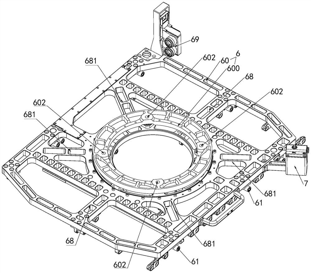
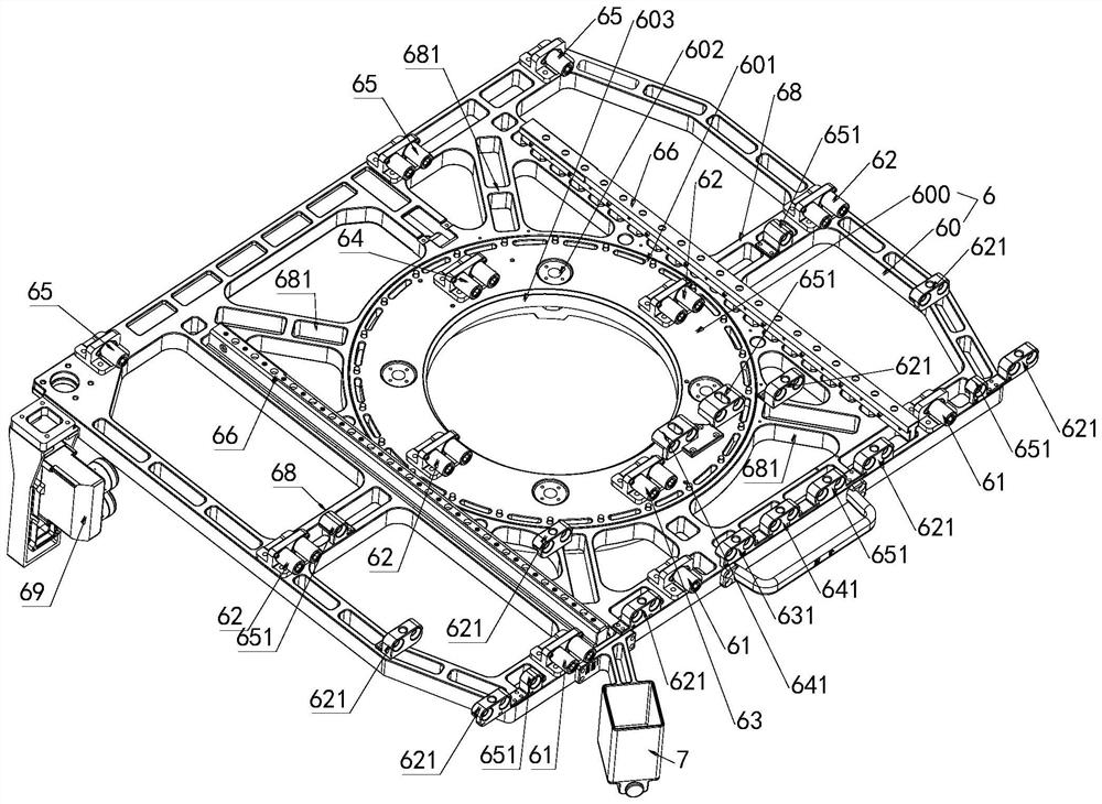
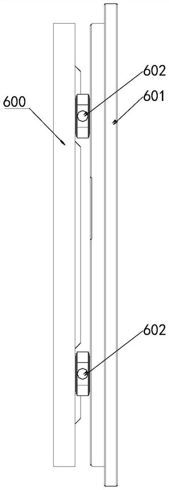
[0049] like Figure 1 to Figure 9 As shown, a space-on-orbit centrifuge stator support assembly in this embodiment includes a support frame 6, and the front end, middle and rear end of one side of the support frame 6 are respectively provided with front end connecting bolts 61, middle connecting bolts and rear end connecting bolts 61. The end connecting bolt 65 is provided with a first guide seat on one side of the support frame 6 corresponding to the front side of the middle connecting bolt, and a second guide seat is provided on one side of the support frame 6 corresponding to the front side of the rear end connecting bolt 65 651; one side surface of the support frame 6 is provided with a guide rail 66 arranged in the front-rear direction, and a stator assembly hole 67 is provided in the middle of the other side surface of the support frame 6.

[0050] like figure 1 and figure 2 As shown, the middle connecting bolts in this embodiment include middle connecting bolts 62, m...

Embodiment 2

[0077] like Figure 10 As shown, a centrifuge in this embodiment includes the space-on-orbit centrifuge stator support assembly described in Embodiment 1, and also includes a turntable 4 and a drive device 5 , and the stator of the drive device is assembled on the support frame 6 In the stator mounting hole 67 in the middle of the other side of the , that is, it is mounted in the stator mounting hole 67 of the balance measuring force table, and the turntable 4 is mounted on the rotor of the driving device.

[0078] In the centrifuge of this embodiment, the supporting assembly can be used to effectively and stably support the driving device, and the components such as the driving device and the turntable can be stably and compactly assembled on the inner wall of the cabinet.


PUM


Abstract

The stator supporting assembly comprises a supporting frame, and the front end, the middle and the rear end of one side face of the supporting frame are provided with a front end connecting bolt, a middle connecting bolt and a rear end connecting bolt correspondingly. A first guide seat is arranged on one side surface of the support frame corresponding to the front side of the middle connecting bolt, and a second guide seat is arranged on one side surface of the support frame corresponding to the front side of the rear end connecting bolt; a guide rail is arranged on one side face of the supporting frame in the front-back direction, and a stator assembly hole is formed in the middle of the other side face of the supporting frame. According to the invention, through the arrangement of the guide rails which are arranged front and back, position guidance can be provided for moving, pushing and pulling of the supporting frame in the cabinet body, and the stator supporting assembly can be limited in the horizontal and vertical directions; by arranging the front end connecting bolt, the middle connecting bolt and the rear end connecting bolt, the stator supporting assembly can be effectively and stably supported and fixed in the space station cabinet body.

Description

technical field [0001] The invention relates to the related technical field of space on-orbit, in particular to a space-on-orbit centrifuge stator support assembly and a centrifuge. Background technique [0002] The centrifuge stator support assembly serves as the installation base of the centrifuge module, provides mechanical and electrical installation interfaces for the centrifuge, and provides temporary rotor fixation for the astronauts to replace the scientific experiment module on-orbit. The existing support structures for space-on-orbit centrifuges are complex, and it is difficult to effectively support the centrifuges. SUMMARY OF THE INVENTION [0003] In order to solve one or more of the problems in the prior art, the present invention provides a space-on-orbit centrifuge stator support assembly and a centrifuge. [0004] The technical solution of the present invention to solve the above technical problems is as follows: a space-on-orbit centrifuge stator support...

Claims


Application Information

Patent Timeline
IPC IPC(8): B64G1/66
CPCB64G1/66
Inventor 邵彩云周妍林王珂乔志宏
Owner TECH & ENG CENT FOR SPACE UTILIZATION CHINESE ACAD OF SCI
Why Eureka
Try Eureka