
Drain valve assembly with self-induction leakproofness

A drain valve, self-sensing technology, used in applications, climate sustainability, textiles and papermaking, etc., can solve problems such as poor user experience affecting product reliability and brand trust, screw caps not tightly closed, and inconvenient maintenance. Achieve the effect of improving customer experience, improving reliability, and facilitating maintenance and use

Pending Publication Date: 2022-05-27
NANJING CHUANGWEI HOUSEHOLD ELECTRONICS APPLIANCES LTD
View PDF0 Cites 0 Cited by
  • Summary
  • Abstract
  • Description
  • Claims
  • Application Information

AI Technical Summary

Problems solved by technology

Usually the tightness of the drainage device is ensured by the mechanical cooperation between the screw cap and the valve body. Depending on the customer's perception through the contact with the screw cap, different people's operations will lead to different results, which may cause the customer to misoperate and the screw cap is not closed tightly, resulting in water leakage from the machine, resulting in poor user experience and affecting product reliability and brand trust.
And the traditional drainage device, in order to ensure the tight fit between the screw cap and the valve body, the matching thread of the screw cap and the valve body is designed as a multi-layer thread, which requires customers and maintenance workers to rotate the screw cap many times, making the operation complicated and inconvenient for maintenance

Method used


Image

  • Drain valve assembly with self-induction leakproofness
  • Drain valve assembly with self-induction leakproofness
  • Drain valve assembly with self-induction leakproofness

Examples


Embodiment Construction

[0032] The present invention will be further described below in conjunction with the accompanying drawings.

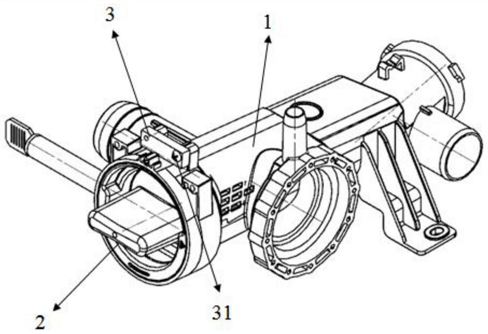
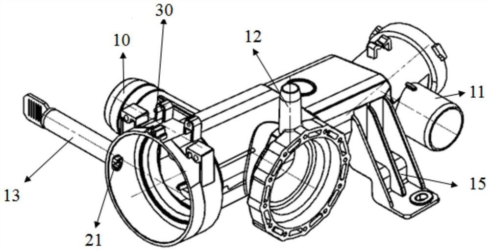
[0033] The drain valve assembly with self-induction airtightness of the present invention includes a drain valve body 1, a self-induction capping assembly 2 mounted with the drain valve body 1, and a drain valve body 1 for sensing the capping position feedback for draining Magnetic switch 3 for valve sealing information.

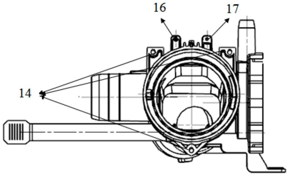
[0034] The drain valve body 1 provides the main structure of the drain valve assembly, and the self-induction screw cap assembly 2 is assembled on the drain valve body 1 through screw fitting. The drain valve body 1 is an integral structure with a water inlet 10, a water outlet 11, a circulating water outlet 12 and an emergency drain outlet 13. The drain valve body 1 is formed with a front fixing bracket 14 at the front and a rear fixing bracket at the rear. 15. The drain valve body 1 is fixed on the whole washing machine by screws by the front fixi...


PUM


Abstract

The invention discloses a drain valve assembly with self-induction leakproofness. The drain valve assembly comprises a drain valve body, a self-induction screw cap assembly and a magnetic sensitive switch, a guide groove is formed in the center horizontal position of the screw cap, and a guide column assembled and matched with the guide groove is arranged on the drainage valve body. A magnetic-sensitive switch fixing left support and a magnetic-sensitive switch fixing right support which are separated from each other are arranged over an opening of the drainage valve body, a magnetic-sensitive switch fixing column is formed on the magnetic-sensitive switch fixing left support, and a threaded hole is formed in the magnetic-sensitive switch fixing right support. The magnetic sensitive switch is positioned through the magnetic sensitive switch fixing column, and the magnetic sensitive switch is installed over the drainage valve body by screwing a magnetic sensitive switch fixing screw into the threaded hole. The self-induction screw cap assembly comprises a screw cap, a magnet and a magnet protection cover, and the magnetic sensing switch senses the position of the magnet in the self-induction screw cap assembly. The accurate position of the screw cap can be sensed and fed back to ensure that the screw cap at the position is tightly matched with the valve body, so that the sealing performance of the drain valve is ensured.

Description

Technical field: [0001] The invention relates to a drain valve assembly with self-induction airtightness, which belongs to the technical field of laundry treatment equipment such as washing machines. Background technique: [0002] In today's clothing processing equipment such as washing machines, the drainage device must be sealed to ensure that the machine does not enter the water and leak water to cause safety problems. Usually, the tightness of the drainage device is ensured by the mechanical cooperation between the screw cap and the valve body. The screw cap must be screwed in place, and the sealing ring on the screw cap and the valve body can be tightly matched to ensure that the valve body is completely sealed; Depending on the customer’s perception through contact with the screw cap, different people’s operations will lead to different results, which may lead to the customer’s misoperation due to the failure of the screw cap to close the screw cap tightly, resulting i...

Claims


Application Information

Patent Timeline
IPC IPC(8): D06F39/08D06F39/10
CPCD06F39/08D06F39/081D06F39/10Y02B40/00
Inventor 周敏朱翔张露邵靖翔刘天文唐佳胤陆启明席磊周国贤吴启楠
Owner NANJING CHUANGWEI HOUSEHOLD ELECTRONICS APPLIANCES LTD
Learn More