Fabricated building climbing frame attachment point position reinforcing assembly

A technology for reinforcing components and attachment points, which is applied in the field of reinforcing components for attachment points of prefabricated building climbing frames, can solve problems such as poor stability, easy to fall off, poor stability, etc., to improve equipment safety, improve the fixing effect, Avoid the effect of shock falling off

Inactive Publication Date: 2022-05-27
江苏鸿恩智能科技有限公司
View PDF0 Cites 0 Cited by
  • Summary
  • Abstract
  • Description
  • Claims
  • Application Information

AI Technical Summary

Problems solved by technology

In the two existing methods, both the nut and the gasket adopt a planar structure. When the fixing bolt is not completely perpendicular to the wall, since the nut and the bolt are vertical, there will inevitably be a gap between the nut and the gasket. Certain angles and gaps not only cannot guarantee the stability of the structural parts on the wall, but also during construction, due to the shaking of the building climbing frame and other bad movements, it is easy to gradually wear and expand due to the existence of the gap, resulting in further deterioration of the stability. In severe cases It is prone to safety accidents such as falling off, and there is no monitoring method for the tightening effect, and it is easy to cause serious safety accidents without the knowledge of the construction personnel
[0004] In view of this, the existing problems are studied and improved, and an attachment point reinforcement component of the prefabricated building climbing frame is provided to solve the existing problems of poor stability and no safety monitoring mechanism, aiming to solve the problem through this technology. Problems and Purpose of Improving Practical Value

Method used


Image

  • Fabricated building climbing frame attachment point position reinforcing assembly
  • Fabricated building climbing frame attachment point position reinforcing assembly
  • Fabricated building climbing frame attachment point position reinforcing assembly

Examples


Embodiment Construction

[0033] To make the object, technical solution and advantages of the present invention more clear and concise, the following in conjunction with specific embodiments and with reference to the accompanying drawings, the present invention is further described in detail. It should be noted that, without conflict, embodiments of the present invention and features in the embodiments may be combined with each other.

[0034] It is understood that these descriptions are exemplary and are not intended to limit the scope of the present invention.

[0035] The following embodiments of the present invention in conjunction with the accompanying drawings are described provided a prefabricated building climbing frame attachment point reinforcement component.

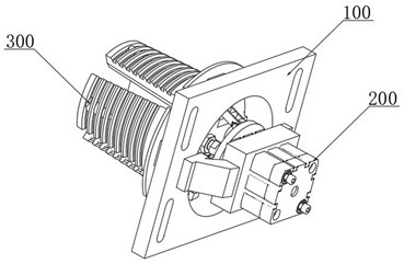
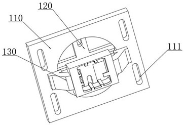
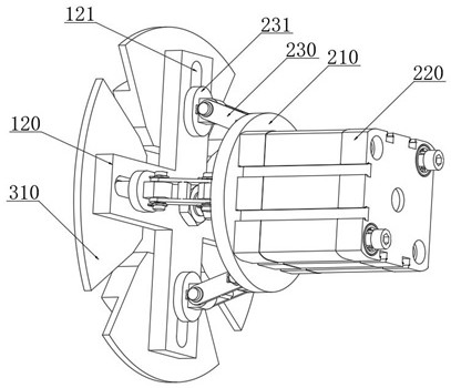
[0036] combine Figure 1-7As shown, the present invention provides a prefabricated building climbing frame attachment point reinforcement assembly, comprising: a rack assembly 100, a hydraulic drive assembly 200 and a hydraulic expansion en...


PUM


Abstract

The assembly type building climbing frame attachment point position reinforcing assembly comprises a rack assembly, a hydraulic driving assembly and a hydraulic expansion end, the hydraulic driving assembly is fixed to the surface of the rack assembly, and the output end of the hydraulic driving assembly is movably connected with the end of the hydraulic expansion end; the rack assembly comprises a building climbing frame positioning plate and a movement guide plate which are welded and fixed to each other, the movement guide plate is fixedly connected to the outer side of the hydraulic driving assembly in a sleeving mode, and a plurality of installation positioning holes are formed in the surface of the building climbing frame positioning plate. According to the device, a hydraulic expansion type joint structure is adopted, an electric hydraulic rod is used for driving a hydraulic expansion end to move in the radial direction towards the periphery under linkage of a linkage rod and a sliding connection lug, the outer wall of an external expansion joint block is firmly attached to the inner wall of a wall face installation hole, and firm installation of a whole pile foundation attachment point position is guaranteed; the expansion force can be increased in real time, so that the point position reinforcing effect is enhanced, and the fixing effect of the attached point position is improved.

Description

Technical field [0001] The present invention relates to the technical field of building climbing frame, specifically a prefabricated building climbing frame attachment point reinforcement component. Background [0002] Building climbing frame, also known as lifting frame, according to its power source can be divided into hydraulic type, electric type, human hand pull type and other main categories. It is a new type of building climbing frame system developed in recent years, mainly used in high-rise shear wall real estate, it can climb or fall along the building, this system makes the scaffolding technology completely changed: one is not necessary to flip the shelf; the second is to eliminate the scaffolding disassembly process, once assembled has been used until the completion of the construction, and is not limited by the height of the building, greatly saving manpower and materials, and in the safety point of view, there is also a great improvement in the traditional scaffoldi...

Claims


Application Information

Patent Timeline
Patent Type & Authority Applications(China)
IPC IPC(8): E04G5/04
CPCE04G5/046
Inventor 刘浩然
Owner 江苏鸿恩智能科技有限公司
Why Eureka
Try Eureka