
Wind power generation device

A technology of wind power generation device and flow divider, which is applied in the mechanical field to achieve the effect of improving conversion efficiency, preventing escape, and reducing manufacturing and product costs

Pending Publication Date: 2022-05-27
黎金明
View PDF0 Cites 0 Cited by
  • Summary
  • Abstract
  • Description
  • Claims
  • Application Information

AI Technical Summary

Problems solved by technology

[0003] In order to solve the above technical problems, the present invention provides a wind power generation device to solve the problem of how to improve the working safety of the equipment and reduce the loss of components

Method used


Image

  • Wind power generation device
  • Wind power generation device
  • Wind power generation device

Examples


Embodiment Construction

[0043] The technical solutions in the embodiments of the present disclosure will be clearly and completely described below with reference to the accompanying drawings in the embodiments of the present disclosure. Obviously, the described embodiments are part of the embodiments of the present disclosure, but not all of the embodiments. Based on the embodiments in the present disclosure, all other embodiments obtained by those skilled in the art without creative efforts shall fall within the protection scope of the present disclosure.

[0044] The specific embodiments of the present disclosure will be described in detail below with reference to the accompanying drawings.

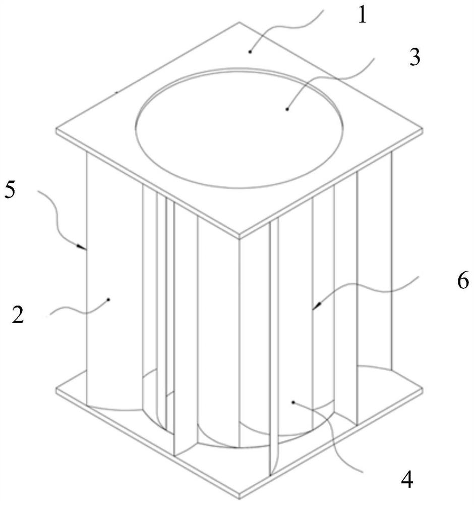
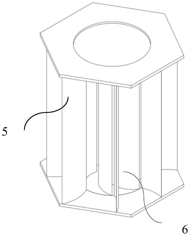
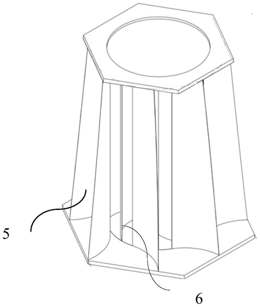
[0045] refer to figure 1 , shows a schematic structural diagram of a wind power generation device, including: a baffle 1, a number of deflectors 2, a blade disk 3 and a number of blades 4;

[0046] Specifically, the baffles 1 are arranged opposite to each other, and are respectively arranged at both ends of a...


PUM


Abstract

The invention relates to a wind power generation device. The wind power generation device comprises oppositely arranged flow separation plates; the multiple flow guide plates are arranged between the flow separation plates at intervals around the normal center lines of the flow separation plates; the wheel blade discs are oppositely arranged, are located between the flow separation plates and are rotationally connected with the flow separation plates; the plurality of wheel blades are arranged among the wheel blade discs at intervals around the normal center lines of the wheel blade discs, and hollow spaces are formed by the wheel blade discs and the wheel blades; the manufacturing and product cost is reduced; the flow separation plate and the wheel blade disc can block wind power flow entering the inner rotor, so that the wind power flow does not escape in the vertical direction, the wind power flow is prevented from escaping in the vertical direction, design parameters are simple and effective, and the conversion efficiency of wind energy and electric energy is effectively improved.

Description

technical field [0001] The invention belongs to the technical field of machinery, and more specifically, particularly relates to a wind power generation device. Background technique [0002] At present, wind power generation is widely used as a clean energy source. Wind power generation is divided into horizontal axis wind turbines and vertical axis wind turbines. In most horizontal axis wind turbines, in order to achieve variable pitch processing during blade rotation In the prior art, a servo motor can be used to adjust the blade pitch angle through a worm gear reducer, thereby improving the utilization rate of wind energy, but the more movable parts, the higher the manufacturing cost and the greater the chance of failure. Vertical axis wind turbines use fixed blades and arrangements to simplify the structure, but because the blades rotate downwind while the opposite blades are subjected to upwind resistance, the wind energy utilization rate is lower than that of horizonta...

Claims


Application Information

Patent Timeline
IPC IPC(8): F03D9/25F03D3/04F03D3/06
CPCF03D9/25F03D3/0427F03D3/062Y02E10/74
Inventor 黎金明
Owner 黎金明
Learn More