Supporting device and method capable of eliminating backlash

A support device and anti-backlash technology, applied in the field of machinery, can solve problems such as complex operation, equipment damage, and non-adaptive clearance elimination, and achieve the effect of complete clearance elimination and simple operation

Pending Publication Date: 2022-05-27
XIAN QINGAN ELECTRIC CONTROL
View PDF0 Cites 0 Cited by
  • Summary
  • Abstract
  • Description
  • Claims
  • Application Information

AI Technical Summary

Problems solved by technology

[0004] 1. By adding an adjustment washer between the support device and the mounting plate, adjust the height of the roller to eliminate the gap. This method adjusts the gap, because the number of support devices is generally large, the operation is more complicated, and stepless adjustment cannot be realized. After the adjustment is completed, The gap will be generated again, and the gap cannot be eliminated adaptively
[0005] 2. A spring is added between the rollers, and the height of the rollers is adjusted through spring compression. This method realizes the stepless adjustment of the gap, and the gap is completely eliminated. However, the load of the equipment is applied to the spring, and the equipment is supported by the elastic force of the spring. The equipment is loaded, unloaded, and transported. If the equipment shakes during the process, the equipment will be damaged.

Method used


Image

  • Supporting device and method capable of eliminating backlash
  • Supporting device and method capable of eliminating backlash
  • Supporting device and method capable of eliminating backlash

Examples


Embodiment

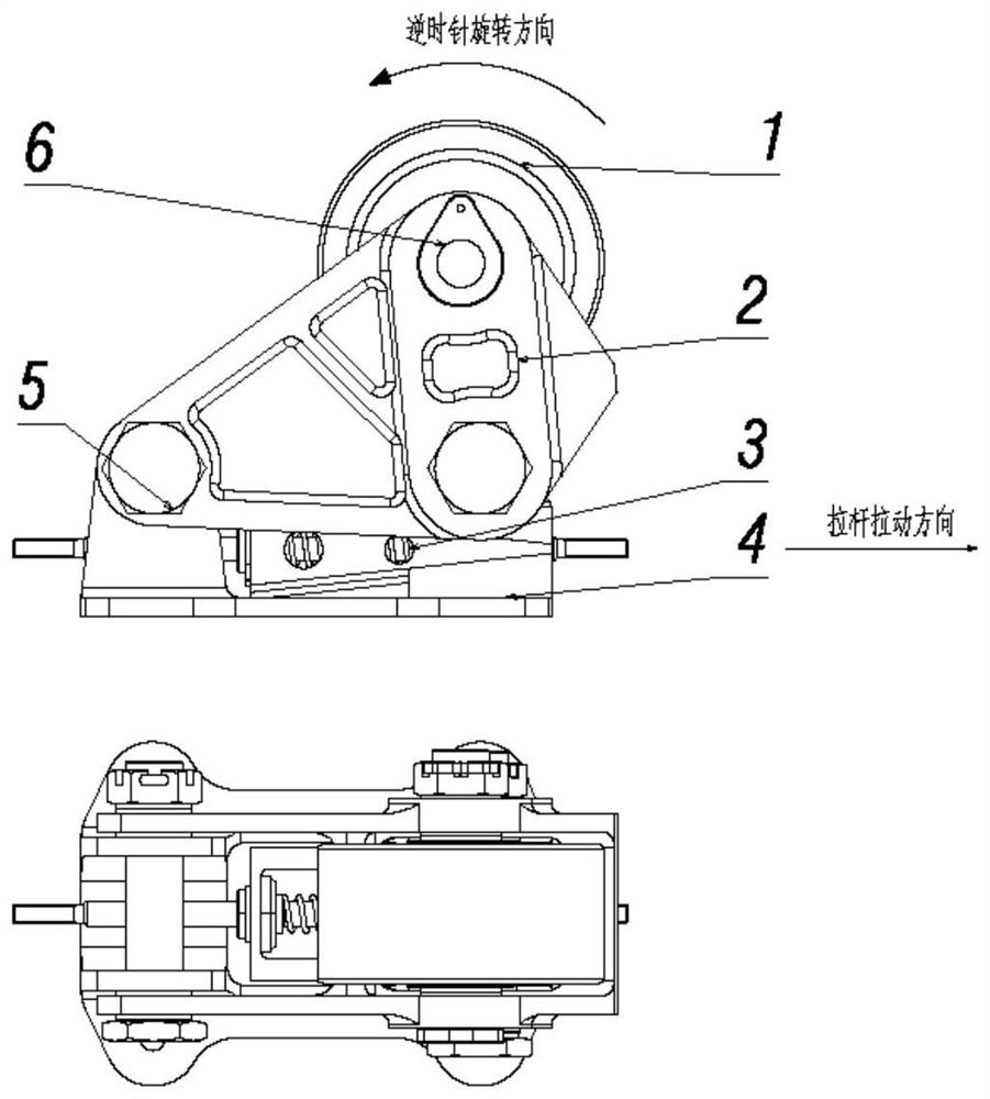
[0039] Reference Figure 1 As shown, a voidable support device of the present invention comprises a roller assembly 1, an upper slider assembly 2, a middle slider assembly 3 and a slider assembly 4, a slider assembly 4 is located at the bottom of the support device, as a support member of other components; roller assembly 1 is mounted above the slider assembly 4 by the upper slider assembly 2, the middle slider assembly 3;

[0040] Reference Figure 5As shown, the slider assembly 4 comprises a base 16 and a sliding block 18, the base 16 is a flat structure, one end of the upper surface is provided parallel to two ear segments, the side wall of the two ear segments is opened with coaxial through holes; the sliding block 18 is a rectangular structure with a top surface of the inclined surface, fixed to the other end of the upper surface of the base 16 by screw 17, the length direction of which is consistent with the length direction of the base 16, located on the outer side of the bas...


PUM


Abstract

The invention discloses a supporting device and method capable of eliminating backlash, and belongs to the technical field of machinery. Comprising a roller assembly, an upper sliding block assembly, a middle sliding block assembly and a lower sliding block assembly, and the lower sliding block assembly is located at the bottom of the supporting device and serves as a supporting component of other components; the rear end of the upper sliding block assembly is hinged to the rear end of the lower sliding block assembly, the middle sliding block assembly is located between the front middle portion of the upper sliding block assembly and the front middle portion of the lower sliding block assembly, and the upper inclined face and the lower inclined face are installed in a matched mode through sliding grooves and sliding rail structures so that the middle sliding block assembly can slide along sliding rails of the upper sliding block assembly and the lower sliding block assembly. Therefore, the upper sliding block assembly and the rolling wheel assembly are driven to rotate anticlockwise, the rolling wheel assembly moves in the vertical direction to make contact with equipment, and clearance elimination is completed. The whole process is stable in transition, and equipment cannot be shaken; and the pulling force in the pulling process is adjustable, different pulling forces are applied according to different weight equipment, and clearance elimination of various equipment can be met. And self-locking is achieved through a wedge-shaped structure, and the supporting effect on equipment is achieved.

Description

Technical field [0001] The present invention belongs to the field of mechanical technology, specifically relates to a voidable support device and method. Background [0002] Support device for loading and unloading and supporting the volume, weight of the equipment, the support device through the bracket installation roller for equipment support, the use of a single roller support, due to the large size of the equipment, the number of support devices used is larger, due to the large installation error, the roller and the equipment can not be fully contacted, part of the roller and the equipment there is a gap. When the equipment is loaded, unloaded and transported, the support device is unevenly loaded, resulting in damage to the roller structure. In order for the support device to be evenly loaded during loading, unloading and transportation, when the support device is installed, the gap between the roller and the equipment must be eliminated. [0003] At present, there are two ...

Claims


Application Information

Patent Timeline
IPC IPC(8): F16C13/00F16M11/04
CPCF16C13/00F16M11/04
Inventor 石磊吴立鹏李强李乐坤
Owner XIAN QINGAN ELECTRIC CONTROL
Why Eureka
Try Eureka