
Automatic focusing motor and camera module

An automatic and moving part technology, applied in the field of optics, can solve problems affecting the imaging quality of the optical imaging system, high energy consumption of the spring suspension structure, image or video jitter, etc., to achieve improved optical imaging effects, light weight, and overall light weight Effect

Pending Publication Date: 2022-05-27
北京可利尔福科技有限公司
View PDF1 Cites 0 Cited by
  • Summary
  • Abstract
  • Description
  • Claims
  • Application Information

AI Technical Summary

Problems solved by technology

However, this spring-type structure causes the lens to deflect during movement, so that it cannot always move in the specified direction, resulting in shaking of the captured image or video, which affects the imaging quality of the optical imaging system
In addition, the structure with spring suspension has high energy consumption, and the system is prone to resonance when applying closed-loop control, which is difficult to control

Method used


Image

  • Automatic focusing motor and camera module
  • Automatic focusing motor and camera module
  • Automatic focusing motor and camera module

Examples


Embodiment Construction

[0035] The specific embodiments of the present disclosure will be described in detail below with reference to the accompanying drawings. It should be understood that the specific embodiments described herein are only used to illustrate and explain the present disclosure, but not to limit the present disclosure.

[0036] In the present disclosure, unless otherwise stated, directional words such as "upper, lower, left and right" are defined according to the direction of the drawing, and "inner" and "outer" refer to the corresponding parts themselves in outline. Terms such as "first", "second", etc., are used in this disclosure to distinguish one element from another and are not of order or importance. Furthermore, when the following description refers to the drawings, the same reference numbers in different drawings refer to the same or similar elements.

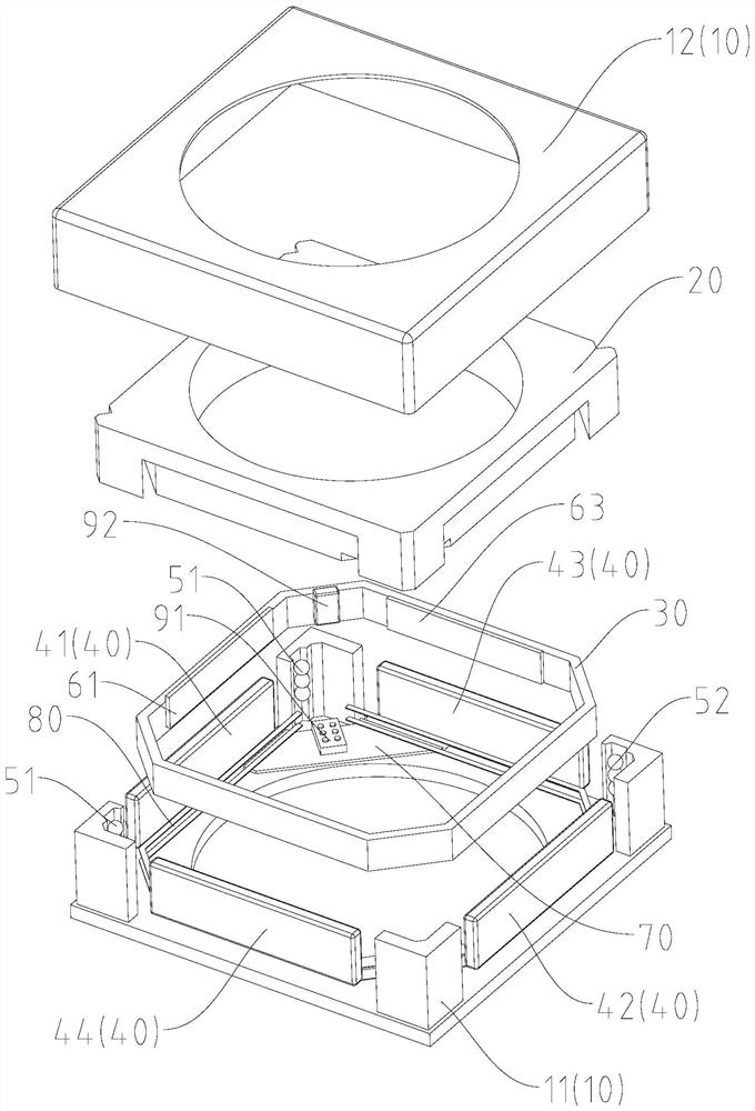
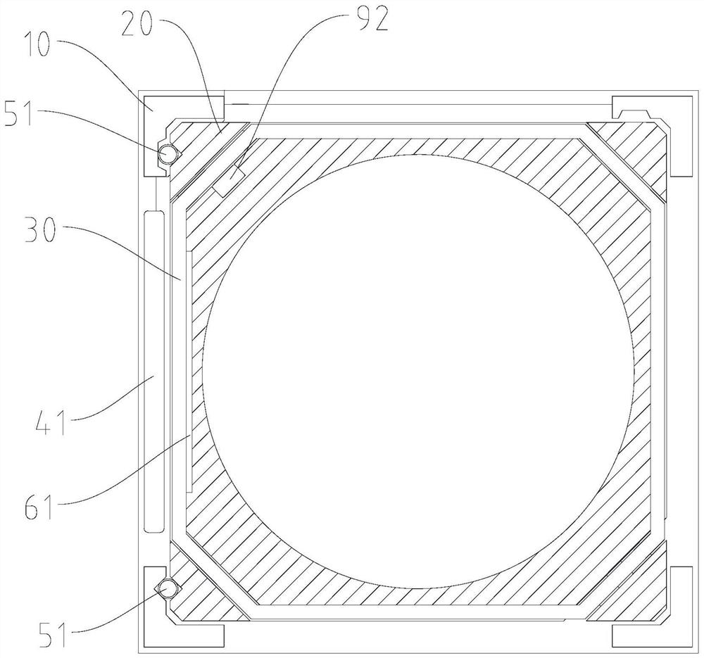
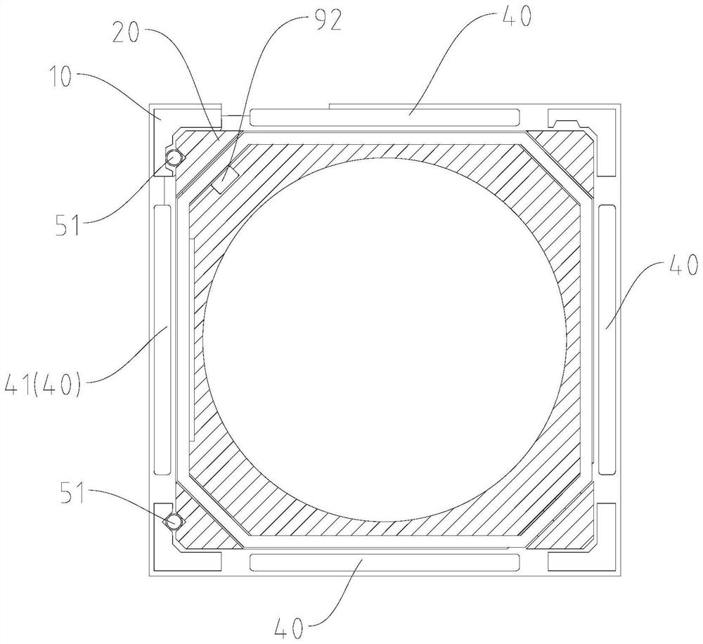
[0037] like Figure 1 to Figure 8 As shown, the present disclosure provides an autofocus motor including a fixed part 10 ...


PUM


Abstract

The invention relates to an automatic focusing motor and a camera module, and the motor comprises a fixed part which comprises a pedestal and a housing covering the periphery of the pedestal; the moving part is movably mounted on the base; the coil is wound in the circumferential direction of the moving part; the magnet is arranged on the fixed part and can generate electromagnetic induction with the coil so as to drive the moving part to move along a preset direction relative to the fixed part; the first supporting part is arranged between the fixed part and the moving part in a contact mode and arranged on one side of the motor, the magnets comprise first magnets arranged on the side, corresponding to the first supporting part, of the fixed part, a first magnetic piece is arranged on the side, opposite to the first magnets, of the coil, and the first magnetic piece can generate magnetic attraction force with the first magnets; therefore, the first supporting part is pressed between the fixed part and the moving part. The motion process of the motor is stable, the imaging effect is improved, the magnetic field utilization rate is increased, the driving force is increased, and the motion part is light in weight, small in inertia and high in response speed.

Description

technical field [0001] The present disclosure relates to the field of optical technology, and in particular, to an autofocus motor and a camera module. Background technique [0002] An optical system is a system used for imaging or optical information processing. It can be used in various fields, such as mobile phone cameras, cameras or lenses of projection technology. With the wider application of optical systems, users are more The pursuit of high-definition imaging optical systems, for this reason, the application of autofocus function is favored by the majority of consumers. The auto-focusing process of the optical device is to drive the optical device to move in a predetermined direction, such as moving along the optical axis, to change the focal length. In the related art, the structure of the spring-suspended lens is usually used in conjunction with the driving unit to drive the movement of the lens to realize automatic focusing. For example, Chinese Patent Applicati...

Claims


Application Information

Patent Timeline
Patent Type & Authority Applications(China)
IPC IPC(8): G02B7/09G03B13/36G03B5/00G02B27/64H02K33/18
CPCG02B7/09G03B13/36G03B5/00G02B27/646H02K33/18
Inventor 董怿
Owner 北京可利尔福科技有限公司
Learn More