Pressure relief method of pressure relief device of switch cabinet

一种泄压装置、开关柜的技术,应用在开关装置的设置、开关装置、变电站/开关装置的冷却/通风等方向,能够解决浪费资源、开关柜炸裂、增加泄压成本等问题,达到节约泄压成本、减小泄压负担、减少浪费的效果

Inactive Publication Date: 2022-05-27
段智强
View PDF0 Cites 2 Cited by
  • Summary
  • Abstract
  • Description
  • Claims
  • Application Information

AI Technical Summary

Problems solved by technology

[0002] The switchgear is a kind of electrical equipment. The external line of the switchgear first enters the main control switch in the cabinet, and then enters the sub-control switch. Each branch is set according to its needs. If a circuit short-circuit fault occurs, under the short-circuit current of tens of thousands of amperes, high-temperature and high-pressure gas will be generated instantaneously. If the high-temperature and high-pressure gas cannot be effectively released in a very short time in a narrow cabinet, it will cause the switch cabinet to burst. The cabinet is damaged, which may endanger personal safety at the same time
[0003] Generally, pressure relief pipes are installed in the switchgear for pressure relief. The bottom of the pressure relief pipe is provided with a connecting plate, which is deformed and broken by high-temperature and high-pressure gas, and then the high-temperature and high-pressure gas is discharged through the pressure relief pipe. The method cannot be reused, and the connecting plate needs to be replaced if it is deformed and broken, which is a waste of resources and increases the cost of pressure relief

Method used


Image

  • Pressure relief method of pressure relief device of switch cabinet
  • Pressure relief method of pressure relief device of switch cabinet
  • Pressure relief method of pressure relief device of switch cabinet

Examples


Embodiment 1

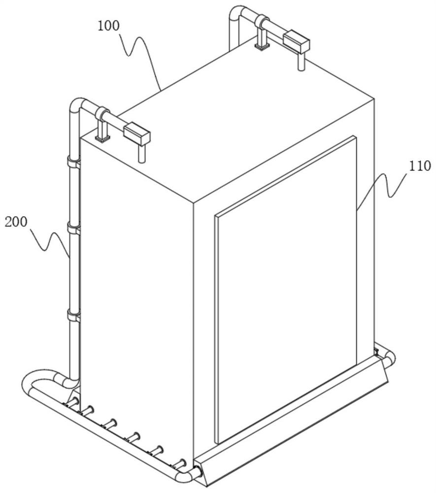
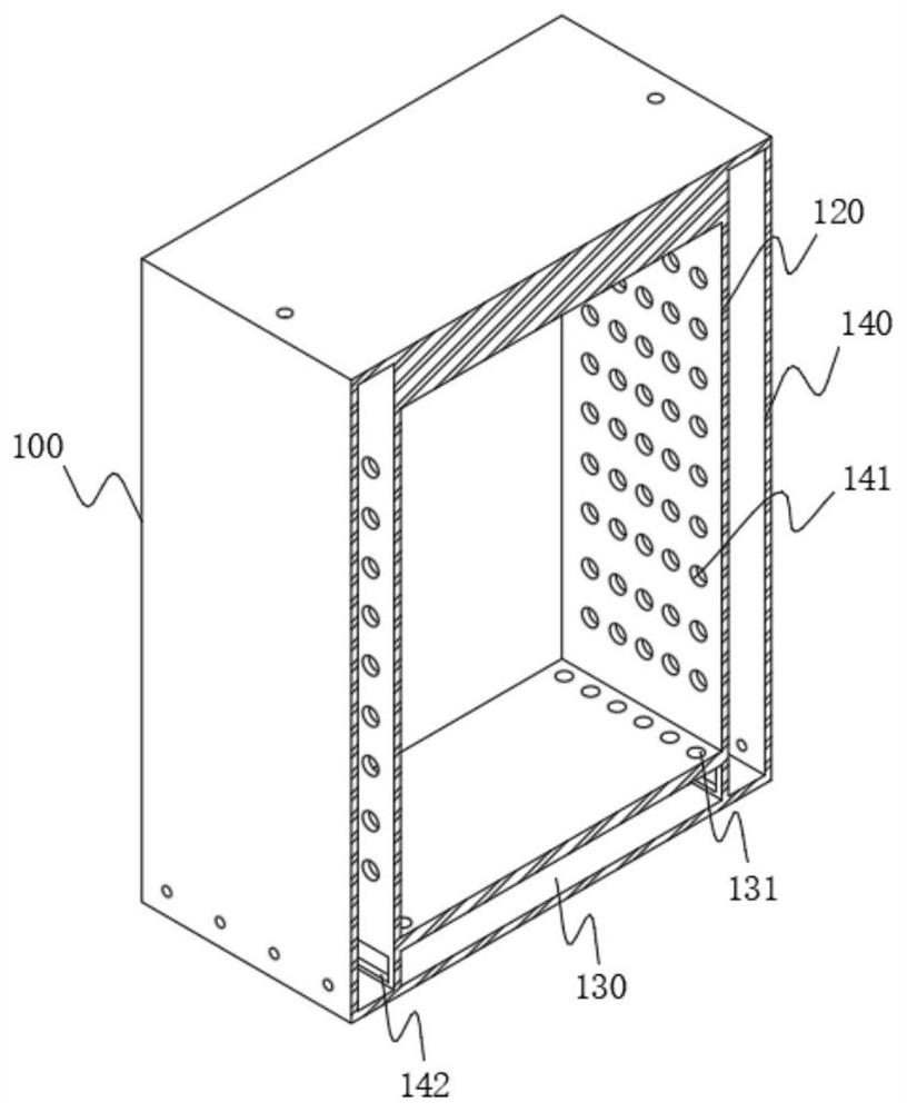
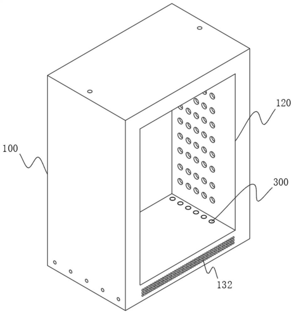
[0055] see Figure 1-Figure 13 As shown, one of the purposes of this embodiment is to provide a safe pressure relief device for a switchgear, including a cabinet body 100, a backflow device 200, and a pressure relief device 300 disposed inside the cabinet body 100. The cabinet body 100 includes a cavity 120 The left and right sides of the cavity 120 are provided with side pressure relief chambers 140, the position between the bottoms of the two side pressure relief chambers 140 is provided with a bottom pressure relief chamber 130, and the side pressure relief chambers 140 and the cavity 120 are arranged in a rectangular shape. There are a plurality of fixed pressure relief holes 141, a chute 142 is provided between the bottom pressure relief chamber 130 and the side pressure relief chamber 140, and a plurality of pressure relief grooves are provided on the side of the top of the bottom pressure relief chamber 130 close to the side pressure relief chamber 140 131. The front si...


PUM


Abstract

The invention relates to the technical field of safety pressure relief, in particular to a pressure relief method of a pressure relief device of a switch cabinet. The safety type pressure relief device of the switch cabinet comprises a cabinet body, a backflow device and a pressure relief device arranged in the cabinet body, the cabinet body comprises a cavity, side pressure relief cavities are formed in the left side and the right side of the cavity, a bottom pressure relief cavity is formed in the position between the bottoms of the two side pressure relief cavities, and a plurality of fixed pressure relief holes are formed between the side pressure relief cavities and the cavity in a rectangular arrangement mode. A sliding groove is formed between the bottom pressure relief cavity and the side pressure relief cavity, a plurality of pressure relief grooves are formed in the side, close to the side pressure relief cavity, of the top of the bottom pressure relief cavity, a front side hole is formed in the front side of the bottom pressure relief cavity, and a rear side hole is formed in the rear side of the front side hole. Through the arranged sealing spring, the sealing plug is reset under the elastic force action of the sealing spring, so that the sealing plug can continue to work during next pressure relief, the purpose of repeated use is achieved, resource waste is reduced, and the pressure relief cost is saved.

Description

technical field [0001] The invention relates to the technical field of safety pressure relief, in particular to a safety pressure relief device for a switchgear and a pressure relief method thereof. Background technique [0002] The switchgear is a kind of electrical equipment. The external line of the switchgear first enters the main control switch in the cabinet, and then enters the sub-control switch. Each branch is set according to its needs. If a circuit short-circuit fault occurs, under the short-circuit current of tens of thousands of amperes, high-temperature and high-pressure gas will be generated instantaneously. If the high-temperature and high-pressure gas cannot be effectively released in a very short time in a narrow cabinet, it will cause the switch cabinet to burst. The cabinet is damaged, which may endanger personal safety. [0003] Generally, pressure relief pipes are installed in the switchgear for pressure relief. The bottom of the pressure relief pipe i...

Claims


Application Information

Patent Timeline
Patent Type & Authority Applications(China)
IPC IPC(8): H02B1/30H02B1/56H02B13/025
CPCH02B1/565H02B1/30H02B13/025
Inventor 段智强
Owner 段智强
Why Eureka
Try Eureka