
Automatic assembling mechanism for shell of charger

An automatic assembly and charger technology, applied in the direction of electric vehicles, electrical components, electrical components, etc., can solve the problems of unstable assembly quality and assembly efficiency, and achieve the effects of simple structure, improved assembly efficiency, efficient positioning and assembly

Active Publication Date: 2022-05-27
南通亚美利电动工具有限公司
View PDF3 Cites 0 Cited by
  • Summary
  • Abstract
  • Description
  • Claims
  • Application Information

AI Technical Summary

Problems solved by technology

[0004] The purpose of the present invention is to provide an automatic assembly mechanism for a charger housing to solve the technical problem of unstable assembly quality and assembly efficiency caused by manual assembly in the prior art

Method used


Image

  • Automatic assembling mechanism for shell of charger
  • Automatic assembling mechanism for shell of charger
  • Automatic assembling mechanism for shell of charger

Examples


Embodiment Construction

[0037] The technical solutions in the embodiments of the present invention will be clearly and completely described below with reference to the accompanying drawings in the embodiments of the present invention. Obviously, the described embodiments are only a part of the embodiments of the present invention, rather than all the embodiments. Based on the embodiments of the present invention, all other embodiments obtained by those of ordinary skill in the art without creative efforts shall fall within the protection scope of the present invention.

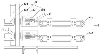
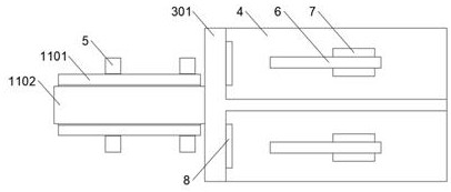
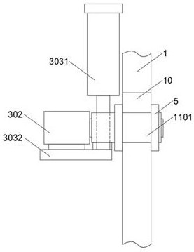
[0038] like Figure 1 to Figure 4 As shown, the present invention provides an automatic housing assembly mechanism for a charger, comprising:

[0039] The calibration board 1 is used for calibrating the initial position of the upper shell and the lower shell of the charger when they are assembled, and the initial position is located on the front side of the calibration board 1 .

[0040] The combined feeding device 2 is arranged in ...


PUM


Abstract

The invention discloses a charger shell automatic assembling mechanism which is provided with a calibration plate used for calibrating the initial position when an upper shell and a lower shell of a charger are assembled, a combined feeding device used for conveying the upper shell and the lower shell to the initial position in front of the calibration plate, and a material receiving and buckling device used for receiving and buckling the upper shell and the lower shell to the initial position in front of the calibration plate. And the material receiving and buckling device is mounted on the calibration plate, is arranged at the tail end of the combined feeding device, and is used for moving the upper shell and the lower shell at the initial position to the standard position and buckling and assembling the upper shell and the lower shell at the standard position. The orientation and posture of the upper shell and the lower shell when the upper shell and the lower shell are received by the receiving and buckling device are preliminarily limited through the calibration plate at the same time, the upper shell and the lower shell are buckled and assembled through the receiving and buckling device, the structure is simple, and efficient positioning and assembling of the upper shell and the lower shell can be achieved.

Description

technical field [0001] The invention relates to the technical field of charger processing, in particular to an automatic assembling mechanism for a shell of a charger. Background technique [0002] A charger usually refers to a device that converts alternating current into low-voltage direct current, which is used to charge small electronic devices and electronic appliances. The charger is generally composed of a charger upper cover, a PCB circuit board and a charger bottom cover with metal pins. [0003] In the prior art, manual assembly is usually used. After the components in the bottom cover, such as the PCB circuit board and the power cord, are installed, the upper cover is manually aligned with the cavity opening end of the bottom cover, and the upper cover and the bottom cover are manually aligned. The connection method of the cover is to fasten the upper cover and the bottom cover or fasten them with screws, but manual assembly has the disadvantage of unstable assem...

Claims


Application Information

Patent Timeline
Patent Type & Authority Applications(China)
IPC IPC(8): H05K13/02H05K13/04
CPCH05K13/0015H05K13/022H05K13/0413H05K13/0419H05K13/0452Y02T10/7072
Inventor 彭海军
Owner 南通亚美利电动工具有限公司
Learn More