Cutting equipment capable of recycling cutting fluid

A technology of cutting equipment and cutting fluid, applied in the field of machine tool parts processing, can solve the problems of effective isolation of cutting chips and cutting fluid, and inability to filter and recycle the cutting chips, so as to reduce processing costs, flexibly isolate and recycle collection, and reduce waste. Effect

Inactive Publication Date: 2022-05-31
南通其诺锯切科技有限公司
View PDF8 Cites 0 Cited by
  • Summary
  • Abstract
  • Description
  • Claims
  • Application Information

AI Technical Summary

Problems solved by technology

[0004] Aiming at the deficiencies of the prior art, the present invention provides a cutting equipment that recycles cutting fluid, which solves the problem that the cutting equipment cannot effectively isolate cutting chips and cutting fluid, and cannot use the mutual attraction between cutting chips and magnetic materials for traction Collection, the problem that cutting chips impregnated with cutting fluid cannot be statically filtered and recycled

Method used


Image

  • Cutting equipment capable of recycling cutting fluid
  • Cutting equipment capable of recycling cutting fluid
  • Cutting equipment capable of recycling cutting fluid

Examples


Embodiment 1

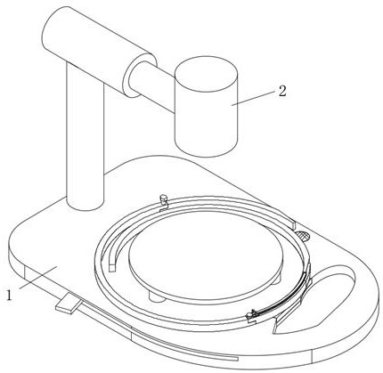
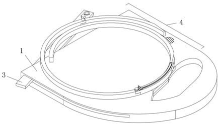
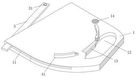
[0030] see Figure 1-7 , the present invention provides a technical solution: a cutting device for circulating cutting fluid, including a base plate 1, a cutting device 2 for cutting a workpiece is installed on the top of the base plate 1, and the middle part of the top surface of the base plate 1 is installed There is an operation bench, and the operation bench is used to limit and fix the workpiece. The inside of the base plate 1 is equipped with a magnetic block swing bar 3, and the middle part of the top of the base plate 1 is installed with a loop assembly 4. The top surface of the base plate 1 is close to the side. A pyramid drain plate 13 is installed at the side position, and the pyramid drain plate 13 is used for secondary filtration and recovery of the cutting fluid; the loopback assembly 4 includes a first arc plate 41 for surrounding the operating platform, and one end of the first arc plate 41 An adsorption component 43 is connected, and the adsorption component 4...

Embodiment 2

[0037] Such as Figure 1-7 As shown, the present invention provides a technical solution: a cutting device for circulating cutting fluid, including a base plate 1, a cutting device 2 for cutting a workpiece is installed on the top of the base plate 1, and the top surface of the base plate 1 is An operating bench is installed in the middle, and the operating bench is used to limit and fix the workpiece. The magnetic block swing bar 3 is installed inside the base plate 1, and the loop assembly 4 is installed in the middle of the top of the base plate 1. The top surface of the base plate 1 A pyramid drain plate 13 is installed near the side, and the pyramid drain plate 13 is used for secondary filtration and recovery of cutting fluid; the loopback assembly 4 includes a first arc plate 41 for surrounding the operating platform, and the first arc plate 41 One end of the suction assembly 43 is connected to the adsorption assembly 43, which is used to absorb and gather cutting chips....


PUM


Abstract

The invention discloses cutting equipment capable of recycling cutting fluid, which comprises a base plate, the top end of the base plate is provided with cutting equipment for cutting a workpiece, the middle part of the surface of the top end of the base plate is provided with an operation rack, and the operation rack is used for limiting and fixing the workpiece; the invention relates to the technical field of machine tool part machining. According to the cutting equipment, redundant cutting fluid can be guided to the two groups of filter plates and is recollected into the cutting equipment for secondary recycling through the first guide pipe connected with the lower end of the collecting hopper, so that the cutting fluid output by the cutting equipment can be flexibly isolated, recycled and collected through the whole loopback assembly, waste of the cutting fluid is reduced, and the cutting efficiency is improved. And the machining cost of cutting equipment is reduced.

Description

technical field [0001] The invention relates to the technical field of machine tool parts processing, in particular to a cutting device for circulating cutting fluid. Background technique [0002] Cutting equipment is an analytical instrument used in the basic disciplines of engineering and technical science. The cutting device has a cleaning water supply mechanism that supplies cleaning water to the workpiece when cutting the workpiece held on the chuck table, and can maintain cleaning. While saving cleaning water consumption; [0003] The cutting equipment on the market cannot effectively isolate cutting chips and cutting fluid, cannot use the mutual attraction between cutting chips and magnetic materials for traction collection, and cannot filter and reuse cutting chips impregnated with cutting fluid. Therefore, we propose a cutting equipment that circulates cutting fluid. Contents of the invention [0004] Aiming at the deficiencies of the prior art, the present inve...

Claims


Application Information

Patent Timeline
Patent Type & Authority Applications(China)
IPC IPC(8): B23D79/00B23Q11/10
CPCB23D79/00B23Q11/1069Y02P70/10
Inventor 刘国珍李纯
Owner 南通其诺锯切科技有限公司
Why Eureka
Try Eureka