
Movable remote control life buoy

A technology of lifebuoy and remote control, which is applied in water lifesaving, ships, ship safety, etc. It can solve problems such as limited accuracy, difficulty in accurately throwing drowning people into the water, and high risk of lifesaver rescue, so as to reduce risks, The effect of reducing the condition requirements of lifesavers and improving the success rate of lifesavers

Pending Publication Date: 2022-05-31
徐伯毅
View PDF0 Cites 0 Cited by
  • Summary
  • Abstract
  • Description
  • Claims
  • Application Information

AI Technical Summary

Problems solved by technology

[0004] 2. The accuracy rate is limited, and drowning people often lose their rationality when drowning. If the lifebuoy cannot fall on the position where the limbs struggle and touch, it is difficult for the drowning person to actively use it. This requires that the lifebuoy throwing requirements be very accurate, but the existing lifebuoys are thrown In the process, it is affected by many factors such as the thrower's own factors, wind strength, distance, terrain, etc., it is difficult to accurately throw the drowning person into the water.
[0005] 3. There is a greater risk of lifesavers going into the water for rescue: lifesavers hold a lifebuoy and go into the water to rescue the drowning person. Due to the local geography and the difficulty of lifesaving, the rescue is carried out under the premise that the rescue is not fully evaluated, and there is still a relatively high risk for the lifesavers.

Method used


Image

  • Movable remote control life buoy
  • Movable remote control life buoy
  • Movable remote control life buoy

Examples


Embodiment Construction

[0029] The following will clearly and completely describe the technical solutions in the embodiments of the present invention with reference to the accompanying drawings in the embodiments of the present invention. Obviously, the described embodiments are only some, not all, embodiments of the present invention. Based on the embodiments of the present invention, all other embodiments obtained by persons of ordinary skill in the art without making creative efforts belong to the protection scope of the present invention.

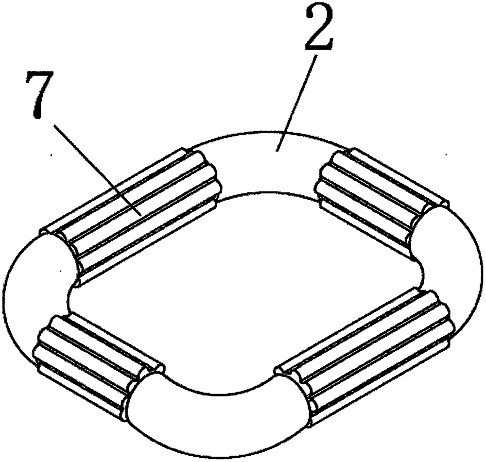
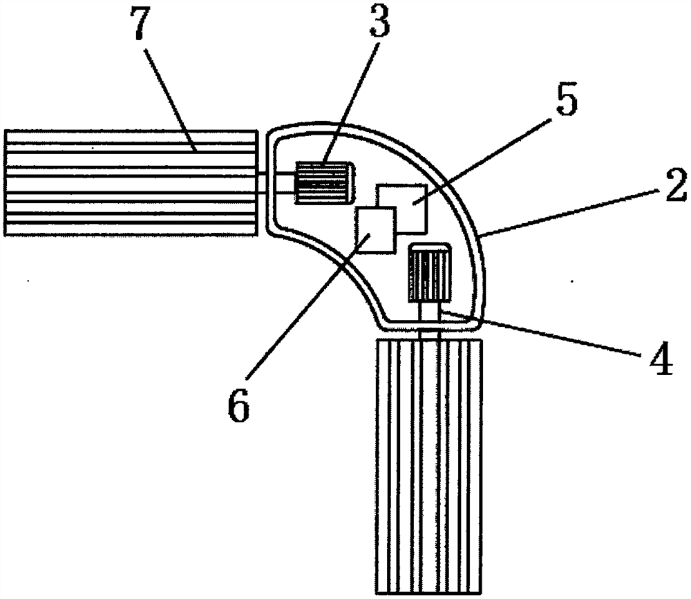
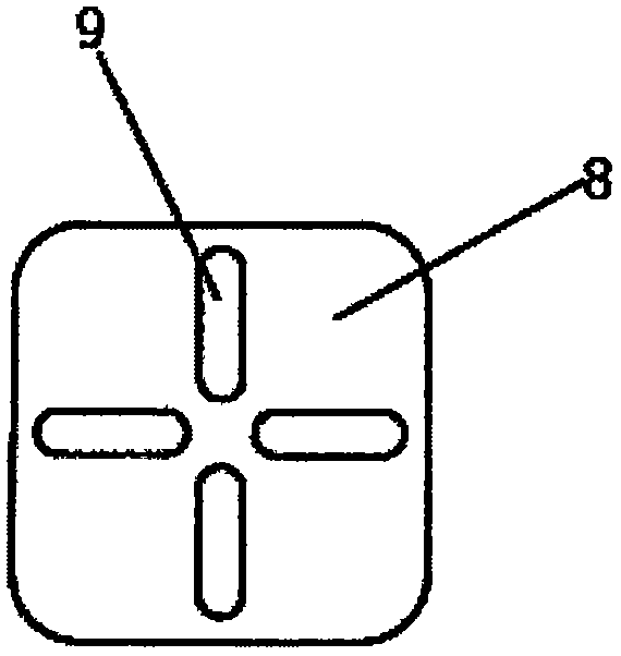
[0030] see Figure 1-5 , a movable remote control life buoy, including a power mechanism, a rotating shaft 1 and a remote controller 8, the power mechanism includes a casing 2, the shape of the casing 2 is L-shaped, and the number of casings 2 is four, and the rotating shaft 1 runs through the casing 2, And the rotating shaft 1 and the shell 2 form a rectangular life buoy, and the two ends inside the shell 2 are fixedly installed with a power motor 3, and the ...


PUM


Abstract

The invention relates to the technical field of life-saving equipment, and discloses a movable remote control life buoy which comprises a power mechanism, a rotating shaft and a remote controller, the power mechanism comprises a shell, power motors are fixedly installed at the two ends of the interior of the shell, and the output ends of the power motors are fixedly connected with rotating rods through splines; the output end of the power motor is fixedly connected with a rotating rod through a spline, one end of the rotating rod is fixedly connected with a rotating shaft, a storage battery is fixedly installed in the middle of the interior of the shell, a controller is installed on the side, close to the storage battery, of the interior of the shell, and tooth-shaped foam is fixedly connected to the surface of the rotating shaft. The movable remote control life buoy can be used for rescuing a drowning person at any distance, and as the life buoy is provided with the power mechanism, the life buoy can be used for rescuing within a remote control range, the influence of uncontrollable factors is reduced, and the life-saving success rate is improved.

Description

technical field [0001] The invention relates to the technical field of lifesaving equipment, in particular to a movable remote control lifebuoy ring. Background technique [0002] Drowning is the most common accident in real life, and there are many drowning tragedies every year; what is even more sad is that many people lose their lives due to their limited conditions or inappropriate rescue methods. The lifebuoy plays an important role in the lifesaving process of the drowning person, but in terms of the existing market lifebuoy, there are the following disadvantages: [0003] 1. The scope of use is limited. Existing lifebuoys mainly carry out lifesaving by throwing, but this is only effective in a short distance, but it is difficult to throw in place if it exceeds 10 meters. If the lifeguard carries the lifebuoy for rescue, the lifebuoy will also slow down the lifesaving time. [0004] 2. The accuracy rate is limited, and drowning people often lose their rationality whe...

Claims


Application Information

Patent Timeline
Patent Type & Authority Applications(China)
IPC IPC(8): B63C9/00B63C9/135
CPCB63C9/00B63C9/135Y02E60/10
Inventor 胡应强邓光品邹骞况雪徐伯毅
Owner 徐伯毅
Learn More