
Arm type centrifugal machine high-centrifugal-force environment high-pressure liquid conveying system

A conveying system and centrifuge technology, applied in pipeline systems, gas/liquid distribution and storage, mechanical equipment, etc., can solve problems such as non-tensile strength, seal failure, fracture, etc. added effect

Active Publication Date: 2022-05-31
ZHEJIANG UNIV
View PDF16 Cites 0 Cited by
  • Summary
  • Abstract
  • Description
  • Claims
  • Application Information

AI Technical Summary

Problems solved by technology

However, the existing high-pressure oil pipes and supporting joints are generally designed to resist internal pressure, and there is no index and capacity for tensile strength. On a centrifuge with large capacity and high centrifugal force, the safety of the basket delivery hose and joints cannot be guaranteed.
With the improvement of the capacity of the experimental device and the increase of the centrifugal force, there is a risk of seal failure or even fracture due to the ultimate failure of the basket delivery hose and joints to withstand the ultra-high centrifugal load

Method used


Image

  • Arm type centrifugal machine high-centrifugal-force environment high-pressure liquid conveying system
  • Arm type centrifugal machine high-centrifugal-force environment high-pressure liquid conveying system
  • Arm type centrifugal machine high-centrifugal-force environment high-pressure liquid conveying system

Examples


Embodiment Construction

[0026] The specific embodiments of the present invention will be described in further detail below in conjunction with the accompanying drawings.

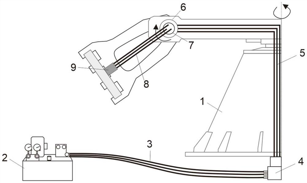
[0027] Such as figure 1 As shown, the present invention provides an arm centrifuge high centrifugal force environment liquid delivery system, which can meet the safe delivery of high pressure oil in the centrifuge basket under the condition of high centrifugal force exceeding 200g. Including centrifuge host 1, ground liquid source 2, ground delivery pipeline 3, centrifuge bottom rotary joint 4, centrifuge rotary arm delivery pipeline 5, rotary arm-basket pin shaft 6, hanging basket rotary joint 7, hanging basket transportation The pipeline 8 and the hanging basket pipeline are connected to the outlet 9.

[0028] The ground liquid source 2 includes a hydraulic pressure source, a water source, etc., and is connected to the stator end of the rotary joint 4 at the bottom of the centrifuge through a ground delivery pipeline 3 through a...


PUM


Abstract

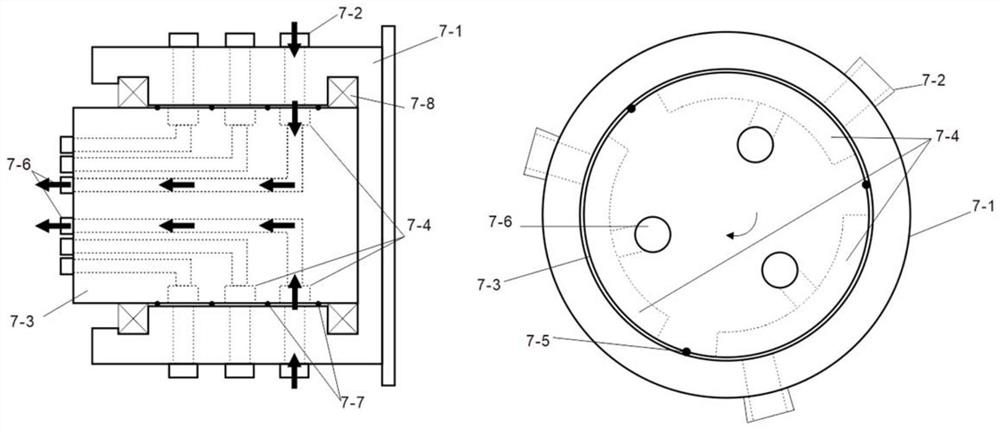
The invention discloses a high-centrifugal-force environment high-pressure liquid conveying system of an arm type centrifugal machine. The system comprises a centrifugal machine main machine, a ground liquid source, a ground conveying pipeline, a centrifugal machine bottom rotating connector, a centrifugal machine rotating arm conveying pipeline, a rotating arm-hanging basket pin shaft, a hanging basket rotating connector, a hanging basket conveying pipeline and a hanging basket pipeline outlet. The hanging basket rotating joint is introduced to adapt to hanging basket-rotating arm angle changes before and after the arm type hanging basket centrifugal machine works, the requirement for water, electricity and oil gas conveying of the centrifugal machine is met, therefore, the pipeline of the centrifugal machine-hanging basket part is solidified, and compared with a traditional scheme that a high-pressure hose is connected into a hanging basket, the centrifugal force load can be increased to 500 g or above. In addition, aiming at the problem of high centrifugal force at the position of the hanging basket rotating joint, the special hanging basket rotating joint is designed by utilizing the working condition that the centrifugal machine hanging basket only fixedly rotates by 90 degrees relative to the rotating arm, the size and the weight of the rotating joint are reduced to 1 / 3 of the original size and weight, and the feasibility and the number of connectable pipelines of the rotating joint at the position of a centrifugal machine pin shaft are greatly increased.

Description

technical field [0001] The invention belongs to the field of geotechnical engineering model tests, in particular to an arm type centrifuge high centrifugal force environment liquid delivery system. Background technique [0002] The arm type geotechnical centrifuge is a kind of test equipment used for the physical simulation test of geotechnical engineering. It simulates the self-gravity stress through the centrifugal force generated by high-speed rotation, so that the stress field in the scaled-scale model of rock and soil carried in the hanging basket is the same as that of the site. Similar to the size of the prototype, simulate the force, deformation and failure of the prototype geotechnical structure to verify the design plan, conduct material parameter research, verify mathematical models and numerical analysis calculation results, and explore new geotechnical engineering physical phenomena. In the field of geotechnical engineering Has been widely used. The relevant ex...

Claims


Application Information

Patent Timeline
Patent Type & Authority Applications(China)
IPC IPC(8): F17D1/08F16L3/015F16L3/22F16L39/06F16L39/02
CPCF17D1/08F16L3/015F16L3/22F16L39/06F16L39/02
Inventor 李金龙凌道盛郑建靖汪玉冰赵宇赵闯王路君王剑闫子壮邱冰静陈云敏
Owner ZHEJIANG UNIV
Learn More