Basalt fiber composite bulletproof plate

A basalt fiber, bulletproof plate technology, applied in protective equipment, armor plate structure, offensive equipment and other directions, can solve the problems of affecting work efficiency, weakening protection ability, low fatigue resistance, etc., to improve work efficiency and reduce difficulty. Effect

Pending Publication Date: 2022-05-31
中北玄武汽车轻量化技术(北京)有限责任公司
View PDF7 Cites 0 Cited by
  • Summary
  • Abstract
  • Description
  • Claims
  • Application Information

AI Technical Summary

Problems solved by technology

[0002] The existing bulletproof plates are basically made of steel, which is heavy and has high maintenance costs. The material has low fatigue resistance. Weak hit
The operating temperature range is small, and the effect of high temperature resistance and low temperature resistance is poor
Weak wave penetration performance, poor anti-aging performance, low fatigue resistance, and the production process is not environmentally friendly
[0003] The size of the existing wallboards is fixed, and splicing is often required, but the splicing is very difficult, a waste of time, and greatly affects work efficiency

Method used


Image

  • Basalt fiber composite bulletproof plate
  • Basalt fiber composite bulletproof plate
  • Basalt fiber composite bulletproof plate

Examples


Embodiment 1

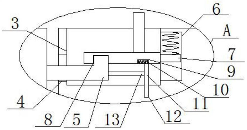
[0021] Reference Figure 1-3, basalt fiber composite bulletproof plate, including the first bulletproof plate 1 and the second bulletproof plate 2, the top and bottom of the second bulletproof plate 2 near the side of the first bulletproof plate 1 is opened with groove 3, the inner wall of the side of the groove 3 is opened with a fixed hole 4, the fixed hole 4 is sliding and mounted with a fixed rod 5, and the fixed rod 5 is in an L-shaped structure, one end of the fixed rod 5 extends to the inside of the groove 3, the other end of the fixed rod 5 extends to the outside of the groove 3, and the fixed rod 5 extends to the end outside the groove 3 and the side of the first bulletproof plate 1 is fixedly connected, Fixing rod 5 is used for fixing.

[0022] In the present invention, one side of the groove 3 is provided with a sliding groove 6, the sliding groove 6 is installed with a sliding block 7, the top of the sliding block 7 is fixed with one end of the first spring, the other e...

Embodiment 2

[0028] Basalt fiber composite bulletproof plate, comprising the first bulletproof plate 1 and the second bulletproof plate 2, the top and bottom of the second bulletproof plate 2 near the first bulletproof plate 1 side chiseled groove 3, groove 3 side of the inner wall chiseled with a fixed hole 4, the fixed hole 4 sliding mounted with a fixed rod 5, and the fixed rod 5 is L-shaped structure, one end of the fixing rod 5 extends to the groove 3, the other end of the fixing rod 5 extends to the outside of the groove 3, and the fixed rod 5 extends to the end outside the groove 3 and the side of the first bulletproof plate 1 is fixedly connected.

[0029]In the present invention, one side of the groove 3 is chiseled on the inner wall of the sliding groove 6, the sliding groove 6 is mounted with a sliding block 7, the top of the sliding block 7 is fixed welded to one end of the first spring, the other end of the first spring is fixedly connected to the top inner wall of the sliding gro...


PUM


Abstract

The invention belongs to the technical field of bulletproof plates, and particularly relates to a basalt fiber composite bulletproof plate, aiming at the existing splicing problem, the basalt fiber composite bulletproof plate comprises a first bulletproof plate and a second bulletproof plate, grooves are formed in the sides, close to the first bulletproof plate, of the top and the bottom of the second bulletproof plate, and fixing holes are formed in the inner walls of one sides of the grooves; a fixing rod is slidably installed in the fixing hole, the fixing rod is of an L-shaped structure, one end of the fixing rod extends into the groove, the other end of the fixing rod extends out of the groove, the end, extending out of the groove, of the fixing rod is fixedly connected with one side of the first bulletproof plate, a sliding groove is formed in the inner wall of one side of the groove, and a sliding block is slidably installed in the sliding groove; and one end of a first spring is fixedly mounted at the top of the sliding block. The first bulletproof plate and the second bulletproof plate are fixedly connected through the fixing rods, so that the splicing difficulty is greatly reduced, and meanwhile, the working efficiency is greatly improved.

Description

Technical field [0001] The present invention relates to the field of bulletproof plate technology, in particular to basalt fiber composite bulletproof plates. Background [0002] The existing bulletproof plate is basically made of steel, heavy weight, high maintenance cost, low fatigue resistance of the material, with the growth of use time, strength decreases, the overall use time is short, the resistance to high-speed impact is reduced, the protection ability is weakened, and the resistance to multiple strikes is weak. The use temperature range is small, and the effect of high temperature and low temperature resistance is poor. Weak wave transmission performance, poor anti-aging performance, low fatigue resistance, production process is not environmentally friendly. [0003] The size of the existing wall panels is a certain amount, and it is often necessary to splice, but the difficulty of splicing is large, which is a waste of time and greatly affects the work efficiency. Con...

Claims


Application Information

Patent Timeline
Patent Type & Authority Applications(China)
IPC IPC(8): F41H5/04
CPCF41H5/0478
Inventor 唐明赵学文王爱军王贵旺
Owner 中北玄武汽车轻量化技术(北京)有限责任公司
Why Eureka
Try Eureka