Passive ventilation device for resident house
A technology for ventilation devices and houses, which is applied in ventilation systems, space heating and ventilation, engines, etc., and can solve the problems of poor wind capture ability of ventilators, changing indoor environment, and low speed of ventilators, etc.
- Summary
- Abstract
- Description
- Claims
- Application Information
AI Technical Summary
Problems solved by technology
Method used
Image

Examples
Embodiment 1
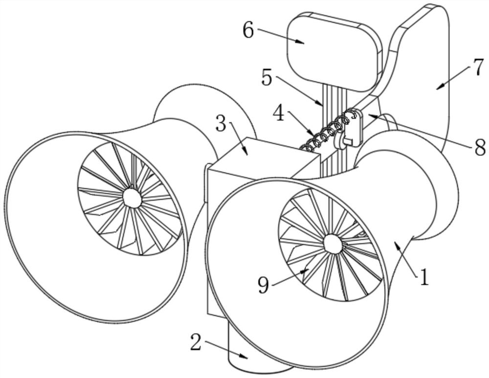
[0032] Refer to the attached Figure 1-8 , a passive ventilation device for residential houses, comprising a casing 3, a casing 2 and two wind catching hoods 1, the two wind catching hoods 1 are fixedly connected with an elbow 12, and the side wall of the casing 3 is connected with the installation port through the installation port. The pipe wall of the elbow 12 is fixedly connected, the lower end of the shell 3 is sleeved with the upper end of the casing 2 through the round mouth, and the elbow 12 is connected with an air guide mechanism, and the wind guide mechanism uses the wind catching cover 1 to capture the natural wind and make the flow The natural wind is converted into mechanical energy in the wind catcher 1, and the air guide mechanism generates negative pressure in the elbow 12 to discharge the air in the casing 3 and the casing 2. One side of the casing 3 is fixedly connected with a support rod 8, A transmission mechanism is connected to the rod wall of the suppor...
Embodiment 2
[0034] Embodiment 2: What is different based on Embodiment 1 is;
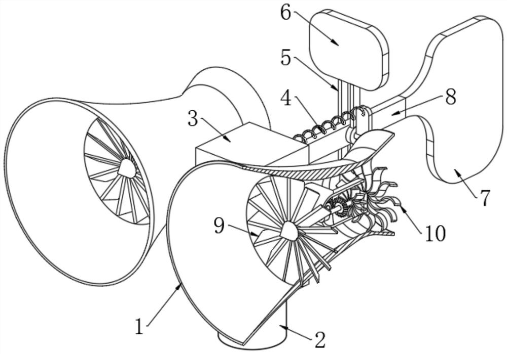
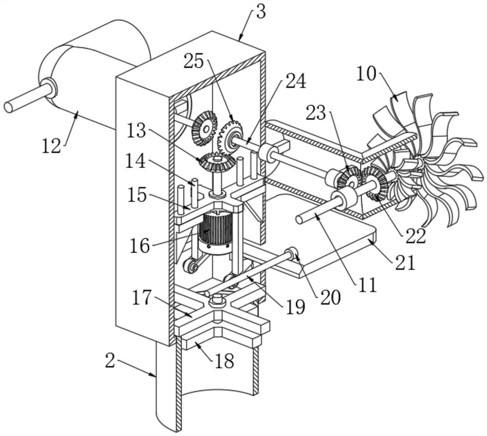
[0035] Refer to the attached Figure 2-6 , the air guide mechanism includes a transmission shaft 11, one end of the transmission shaft 11 is rotatably connected with the bend of the elbow 12 through the first rolling bearing, and one end of the transmission shaft 11 passes through the first rolling bearing and is fixedly connected with the turbofan 9, the transmission shaft 11 The fan blade 30 and the driving gear 22 are fixedly connected to the shaft wall of the shaft, one side of the driving gear 22 is meshed with the driven gear 23, one side of the driven gear 23 is fixedly connected with the horizontal shaft 24, and the shaft wall of the horizontal shaft 24 passes through the two Each bearing seat is rotatably connected to the inner wall of the elbow 12, and the end of the transmission shaft 11 away from the turbo fan 9 is fixedly connected with a fancy fan blade 10. The plurality of blades of the fancy fan...
Embodiment 3
[0038] Embodiment 3: The difference based on Embodiment 1 is;
[0039] Refer to the attached Figure 7 The transmission mechanism includes a transmission frame 5, the upper end of the transmission frame 5 is fixedly connected with a windshield 6, the transmission frame 5 is rotatably connected with the side wall of the support rod 8 through a rotating shaft, and the lower end of the transmission frame 5 is rotatably connected with a support arm 32 through the rotating shaft One end of the support arm 32 is rotatably connected to one end of the horizontal plate 21 through a shaft pin, one end of the horizontal plate 21 extends into the casing 3 and is provided with an inclined surface, and one end of the rotating shaft is fixedly connected with a connecting rod 31. One end of the connecting rod 31 The side is fixedly connected with a tension spring 4, one end of the tension spring 4 is fixedly connected with one side of the casing 3, a positioning block is arranged in the casin...
PUM
 Abstract
Description
Claims
Application Information
 - R&D
- Intellectual Property
- Life Sciences
- Materials
- Tech Scout
- Unparalleled Data Quality
- Higher Quality Content
- 60% Fewer Hallucinations
Browse by: Latest US Patents, China's latest patents, Technical Efficacy Thesaurus, Application Domain, Technology Topic, Popular Technical Reports.
© 2025 PatSnap. All rights reserved.Legal|Privacy policy|Modern Slavery Act Transparency Statement|Sitemap|About US| Contact US: help@patsnap.com