Digital device for computer simulation design and control method
A technology of computer simulation and controller, which is applied in the field of computer simulation, can solve the problems that the device cannot be adjusted freely, and the monitoring and control of the simulation mechanism cannot be simulated, so as to achieve the effect of convenient remote control instructions, convenient mobile base, and improved convenience of use
- Summary
- Abstract
- Description
- Claims
- Application Information
AI Technical Summary
Problems solved by technology
Method used
Image
Examples
Embodiment 1
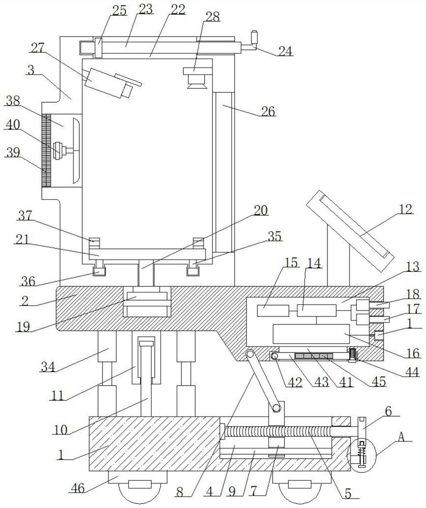
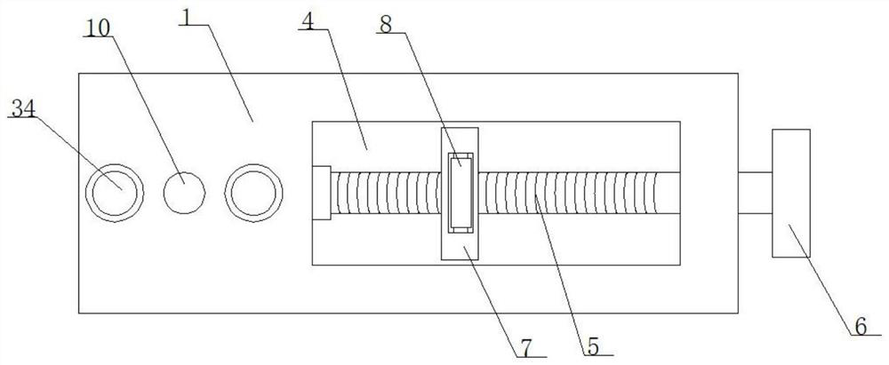
[0038] refer to figure 1 , 2 And 4, a digital device for computer simulation design, including a base 1, a mounting plate 2 and an operation box 3, the bottom of the base 1 is rotatably connected with a plurality of universal self-locking wheels 46, which is convenient for moving the base 1, and the top of the base 1 is provided with a mounting Slot 4. A screw 5 is rotatably connected in the installation slot 4 to drive the slider 7 to slide. One end of the screw 5 penetrates the inner wall of the installation slot 4 and is fixedly connected with a knob 6 to drive the screw 5 to rotate.
[0039] In this embodiment, a locking mechanism corresponding to the knob 6 is fixedly connected to the outer wall of the base 1, which is convenient for fixing the knob 6. One end of the screw rod 5 located in the installation groove 4 is threadedly sleeved with a slider 7, which is used to drive the connecting plate 8 When moving, the slider 7 is connected with the bottom of the mounting pl...
Embodiment 2
[0049] It has the implementation content of the above-mentioned embodiment, wherein, for the specific implementation of the above-mentioned embodiment, reference may be made to the above-mentioned description, and the embodiment here will not be repeated in detail; and in the embodiment of the present application, the difference between it and the above-mentioned embodiment is that :
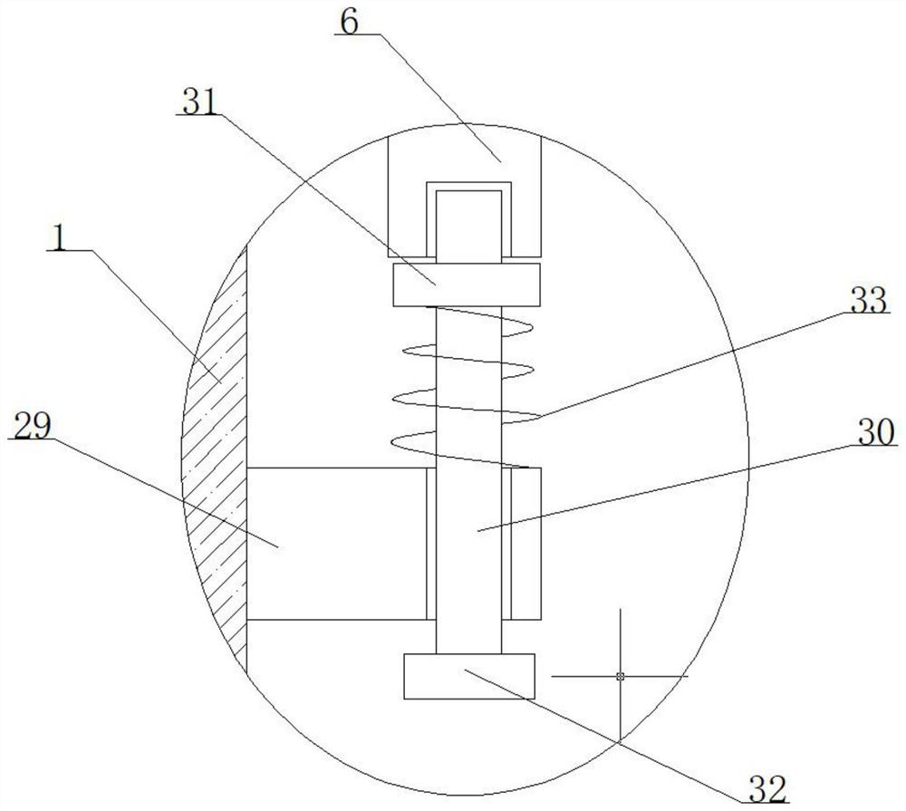
[0050] refer to image 3 , the locking mechanism includes a clamping block 29 and a clamping rod 30. The clamping rod 30 is slidably inserted on the clamping block 29 for fixing the knob 6. The knob 6 is surrounded by a plurality of clamping slots corresponding to the clamping rod 30. One end of the rod 30 close to the knob 6 is fixedly sleeved with a ferrule 31 , one end of the jig 30 away from the ferrule 31 is fixedly connected with a pull rod 32 , a spring 33 is sleeved on the tie rod 30 , and two ends of the spring 33 are respectively connected with the ferrule 31 . It is fixedly connected...
Embodiment 3
[0052] It has the implementation content of the above-mentioned embodiment, wherein, for the specific implementation of the above-mentioned embodiment, reference may be made to the above-mentioned description, and the embodiment here will not be repeated in detail; and in the embodiment of the present application, the difference between it and the above-mentioned embodiment is that :
[0053] A control method of a digital device for computer simulation design, comprising the following steps:
[0054] Step 1: first install the simulation mechanism on the support plate 21, then start the motor 19 to drive the support plate 21 to rotate, and adjust the direction of the simulation mechanism;
[0055] Step 2: Then use the camera 27 to monitor the working condition of the simulation mechanism, and then send the monitoring signal to the controller 14;
[0056] Step 3: The control command is then input through the input module 12 to control the motor 19, thereby realizing multi-angle...
PUM
 Abstract
Description
Claims
Application Information
 - R&D
- Intellectual Property
- Life Sciences
- Materials
- Tech Scout
- Unparalleled Data Quality
- Higher Quality Content
- 60% Fewer Hallucinations
Browse by: Latest US Patents, China's latest patents, Technical Efficacy Thesaurus, Application Domain, Technology Topic, Popular Technical Reports.
© 2025 PatSnap. All rights reserved.Legal|Privacy policy|Modern Slavery Act Transparency Statement|Sitemap|About US| Contact US: help@patsnap.com


