
Drag hook bar modeling tool for complex steel bar engineering

A technology of reinforcement engineering and hook reinforcement, which is applied in the field of modeling tools for tension reinforcement in complex reinforcement engineering, and achieves the effect of fine and efficient modeling.

Pending Publication Date: 2022-06-03
中核华辰建筑工程有限公司
View PDF0 Cites 0 Cited by
  • Summary
  • Abstract
  • Description
  • Claims
  • Application Information

AI Technical Summary

Problems solved by technology

[0005] Based on this, the purpose of the present invention is to provide a complex steel engineering puller tendon modeling tool to solve the problem that the existing modeling tools can achieve the goal of three-dimensional modeling and two-dimensional drawing only through the human-computer interaction interface for a specific structure type. , a technical problem that requires a lot of manual modification and repetitive operations by the user

Method used


Image

  • Drag hook bar modeling tool for complex steel bar engineering
  • Drag hook bar modeling tool for complex steel bar engineering
  • Drag hook bar modeling tool for complex steel bar engineering

Examples


Embodiment 1

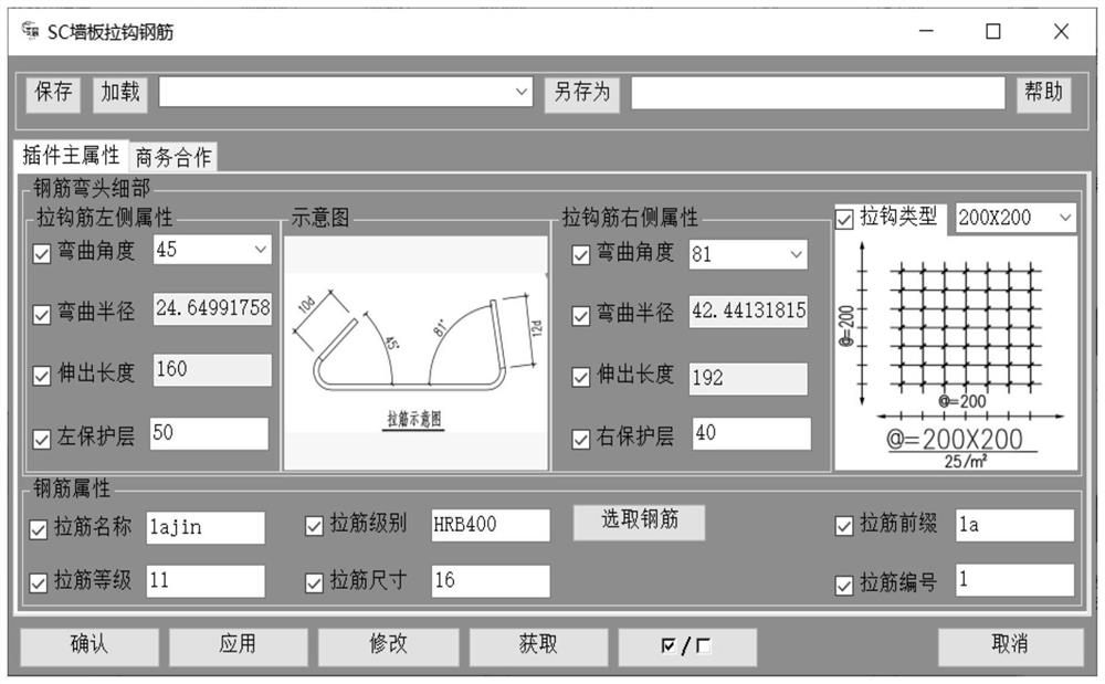
[0022] A modeling tool for drawing hook bars for complex reinforcement engineering. The modeling tool relies on C# development, including a winform interface that can edit and modify data parameters at the front end, which is used for users to adjust the data information of steel bar drawings visible to the human eye. Further, the front-end data parameters The interface includes the important data parameter interface of the steel bar; the back-end design of various functions and method bodies runs as a class library, which is used to accept the parameters input from the front-end data interface, and pass the parameters into the function bodies of various modeling methods, so as to modify the model intelligently at the bottom layer. ;

[0023] Attributes of the front-end tie bars of the modeling tool: The tie bar types include the three types of 200*200, 200*400, and 400*400 specified in the technical specification. Bending angle, radius, length, fit the protective layer of the...

Embodiment 2

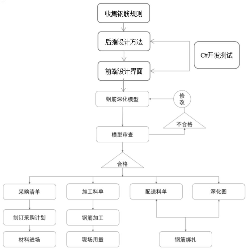
[0026] Modeling tool design and implementation process

[0027] 1. Gather the steel bar rules for wall panel hooks;

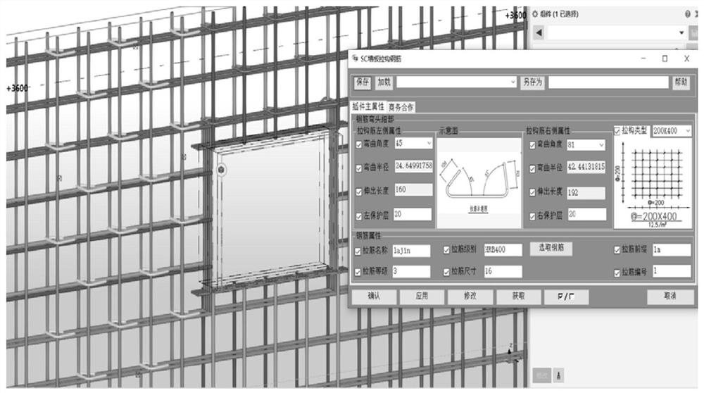
[0028] 2. Begin to use C# to develop tie-bar modeling tools. During the front-end and back-end interactive tests, the rules of wallboard tie-bars are skillfully integrated into the wallboard tie-bar modeling tool. Due to the difficulty of modeling wallboard tie-bars in Tekla software , and even only draw hook bars one at a time, and in complex projects, wall panel hook bars are arranged by area, not by wall, so this modeling tool makes up for the hook bars in Tekla reinforcement modeling. The function of the module makes the modeling more refined and efficient. figure 1 The actual modeling effect diagram for the modeling tool, and the parameter interface in the actual application of the modeling tool. figure 2 The front-end user visual interface after the development of the modeling tool is completed;

[0029] 3. After completing the development of the mode...


PUM


Abstract

The invention discloses a complex steel bar engineering draw hook bar modeling tool which is developed depending on C # and comprises a winform interface capable of editing and modifying data parameters at the front end and used for a user to adjust steel bar drawing data information visible to human eyes; various function method bodies are designed at the rear end to run in a class library and used for receiving parameters input by a front-end data interface, the parameters are transmitted into various modeling method function bodies, and therefore a model is intelligently modified at the bottom layer. According to the method, C # is used for developing a drag hook rib modeling tool, during the period, the front end and the rear end are circularly and interactively tested, a wallboard drag hook rib rule is skillfully fused into the wallboard drag hook rib modeling tool, due to the fact that in Tekla software, wallboard drag hook ribs are difficult to model, even only drag hook ribs can be drawn one by one, the wallboard drag hook ribs are arranged according to areas in complex engineering, and the modeling efficiency is greatly improved. The modeling tool is not arranged according to a wall body, so that the modeling tool makes up the function of a draw hook bar module in Tekla steel bar modeling as much as possible, and modeling is more precise and efficient.

Description

technical field [0001] The invention relates to the field of modeling tools, in particular to a modeling tool for drawing hook bars of complex steel bar engineering. Background technique [0002] Existing rebar engineering calculation software software on the market is based on the flat method for the modeling of the hook bars. When encountering the complex reinforcement engineering modeling of thick walls and slabs, it is not enough to accurately complete the modeling and requires manual calculation, especially when the hook bars are 8 rows. When there are 10 rows of steel bars, the demand cannot be met, resulting in an inaccurate amount of steel bars extracted. There is no intelligent solution when the walls and walls are staggered in the form of hidden columns. [0003] After investigation, Tekla is a platform-based BIM design software with 3D modeling and 2D drawing functions for concrete and steel bars, but for reinforced concrete structures, Tekla is more inclined to p...

Claims


Application Information

Patent Timeline
Patent Type & Authority Applications(China)
IPC IPC(8): G06F30/20G06F119/02
CPCG06F30/20G06F2119/02
Inventor 刘兆兴张琪新谢文王奇黄倩
Owner 中核华辰建筑工程有限公司
Learn More