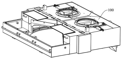
Drainage tank and thinning machine

A drainage box and thinning machine technology, applied in the direction of sustainable manufacturing/processing, climate sustainability, final product manufacturing, etc., can solve the uneven distribution of gaps, increase the failure rate of thinning machines, and affect the normal use of thinning machines and other issues to achieve the effect of avoiding interference and ensuring stable operation

Active Publication Date: 2022-06-03
JIANGSU JCA ELECTRONICS TECH CO LTD
View PDF5 Cites 0 Cited by
  • Summary
  • Abstract
  • Description
  • Claims
  • Application Information

AI Technical Summary

Problems solved by technology

Due to the influence of the inclination angle of the drainage box and the machining accuracy, the gap between the turntable and the assembly hole is unevenly distributed, which will easily cause the

Method used


Image

  • Drainage tank and thinning machine
  • Drainage tank and thinning machine
  • Drainage tank and thinning machine

Examples


Example Embodiment

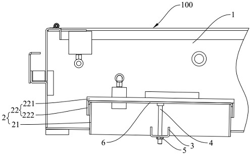
[0035] Further, the connector 3 in this embodiment is channel steel, which does not require additional design and processing, is cheap and easy to obtain, and is beneficial to reducing costs. The two ends of the connector 3 are respectively welded to the bottom plate 1, which enhances the connection strength of the connector 3 and the bottom plate 1, improves the limit value of the tension force transmitted by the connector 3 to the bottom plate 1, and enhances the accessories of the leveling station 10. The deformation amount of the bottom plate 1 improves the leveling effect.

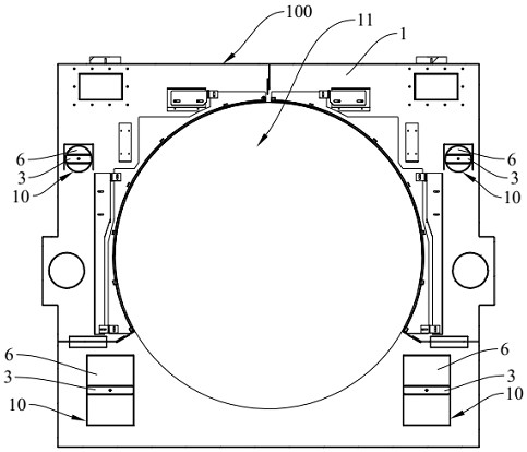
[0036] like figure 2 As shown, the base plate 1 is provided with four leveling stations 10 spaced along the circumferential direction of the mounting hole 11 . Since the four leveling stations 10 are distributed around the assembly hole 11, the area where the inner edge of the assembly hole 11 is located can be leveled, so that the gap between the assembly hole 11 and the turntable is evenly distrib...


PUM


Abstract

The invention relates to the technical field of thinning machines, in particular to a drainage box and a thinning machine. The drainage box comprises a leveling boss, a connecting piece, a pull rod and an adjusting piece, a plurality of leveling stations are arranged on a bottom plate of the drainage box in the circumferential direction of the assembly hole at intervals, the leveling stations are concaved inwards to form the leveling boss with an opening in the bottom, and the side wall of the leveling boss is connected with the bottom plate of the drainage box. The connecting piece is arranged at the opening end of the leveling boss and connected with the bottom plate. One end of the pull rod is fixedly connected with the top wall of the leveling boss, and the other end is movably connected with the connecting piece. The adjusting piece can enable the connecting piece to move in the axial direction of the pull rod and drive the bottom plate close to the leveling station to deform, and therefore the size of the gap between the assembly hole and the rotary table is adjusted. The thinning machine adopts the drainage box, and the bottom plate near the leveling station is leveled through the matching of the adjusting piece and the pull rod so as to level the assembly hole, so that the gap between the assembly hole and the rotary table is uniform and consistent, and the rotary table is prevented from interfering with the assembly hole in the rotating process.

Description

technical field [0001] The invention relates to the technical field of thinning machines, in particular to a drainage box and a thinning machine. Background technique [0002] The thinning machine is a common equipment for thinning processing of wafers. The thinning machine is equipped with a drainage tank for draining the cooling liquid. The drain tank is generally installed obliquely on the casing of the thinning machine, and the inclination angle is about 1°, so that the cooling liquid can be quickly discharged from the drain tank under the action of its own gravity. [0003] At present, the bottom plate of the drainage box is provided with an assembly hole, and the turntable of the thinning machine is inserted in the assembly hole and rotates in the assembly hole to drive the film support table to rotate. Due to the influence of the inclination angle of the drainage box and the machining accuracy, the distribution of the gap between the turntable and the assembly hole i...

Claims


Application Information

Patent Timeline
IPC IPC(8): H01L21/67B28D5/00
CPCH01L21/67011B28D5/0058B28D5/0076Y02P70/50
Inventor 杨云龙王强胡章坤于光明张方伟
Owner JIANGSU JCA ELECTRONICS TECH CO LTD
Why Eureka
Try Eureka