Electric connector, charging pile and charging system

A technology for electrical connectors and joints, applied in electric vehicle charging technology, charging stations, electric vehicles, etc., can solve problems affecting vehicle charging efficiency, achieve excellent insulation and heat conduction effects, prevent leakage, and improve transmission efficiency.

Pending Publication Date: 2022-06-07
AUTEL NEW ENERGY CO LTD
0 Cites 0 Cited by

AI-Extracted Technical Summary

Problems solved by technology

If the heat is not dissipated in time, it will gre...

Method used

[0034] As shown in Figures 3 to 5, they respectively show a perspective view of the electrical connector 100 provided by one embodiment of the application, a perspective view of the electrical connector 100 provided by another embodiment of the application, and another embodiment of the application. A perspective view of the electrical connector 100 provided in one embodiment, combined with other drawings. The electrical connector 100 includes a housing 10 , a joint 20 and a cooling medium (not shown). Wherein, the casing 10 is provided with a receiving cavity 11 and two through holes 12 oppositely arranged. The receiving chamber 11 communicates with the outside world through the through hole 12 . In the embodiment of the present application, the housing 10 is in the shape of a cylinder, and the housing cavity 11 arranged in the housing 10 is similar to the outer contour of the housing 10, so that the internal space of the housing 10 can be fully utilized, and the two-way The hole 12 is relatively arranged on the plane of the cylindrical shell 10, so that the joint 20 can be directly extended into the receiving cavity 11 during production or assembly, and it is convenient for storage, installation and disassembly. The joint 20 includes a first part 21 and a second part 22. The second part 22 is arranged at both ends of the first part 21. The joint 20 is plugged into the housing 10. The first part 21 is located in the receiving cavity 11, and the second part 22 is connected through the through hole. 12 protrudes and is exposed on the outer surface of the casing 10, and the first part 21 is subjected to insulation treatment and heat conduction treatment. The cooling medium is accommodated in the housing cavity 11 . That is, surface treatment is carried out on the first part 21 of the connector 20 plugged into the housing 10, so that the thickness of the connector 20 is constant, and it has the insulation capacity and thermal conductivity that meet the requirements of use, which is increased compared with the prior art. The technical solution of the bushing, this solution reduces thermal resistance, and directly performs heat exchange between the cooling medium and the joint 20 in the accommodation cavity 11, thereby improving the heat exchange efficiency.
[0036] In other embodiments of the present application, please refer to FIG. 3, in conjunction with other accompanying drawings. The electrical connector 100 also includes a first liquid guide tube 30 , both ends of the first liquid guide tube 30 communicate with the receiving cavity 11 , and the cooling medium circulates in the first liquid guide tube...

Abstract

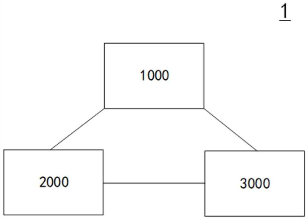
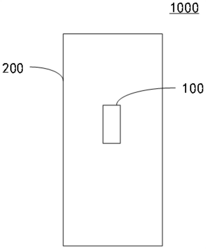
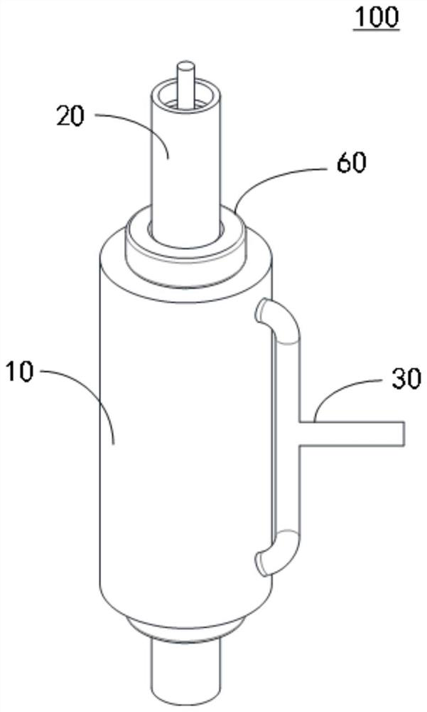
The embodiment of the invention relates to the technical field of electric energy transmission, in particular to an electric connector, a charging pile and a charging system. The electric connector comprises a shell, a joint and a cooling medium, the shell is provided with an accommodating cavity and two oppositely arranged through holes, and the accommodating cavity is communicated with the outside through the through holes. The connector comprises a first part and second parts, the second parts are arranged at the two ends of the first part, the connector is inserted into the shell, the first part is located in the containing cavity, the second parts penetrate out of the through hole and are exposed out of the outer surface of the shell, and the first part is subjected to insulation treatment and heat conduction treatment. The cooling medium is contained in the containing cavity. Through the above structure, after the first part is subjected to surface treatment, excellent insulation and heat conduction effects can be obtained, so that after the joint generates heat, heat is directly dissipated through a cooling medium. Meanwhile, electric leakage of the connector can be effectively prevented after insulation treatment. Therefore, the transmission efficiency of electric energy is improved.

Application Domain

Charging stationsElectric vehicle charging technology

Technology Topic

Electric energyEngineering +3

Image

  • Electric connector, charging pile and charging system
  • Electric connector, charging pile and charging system
  • Electric connector, charging pile and charging system

Examples

  • Effect test(1)

Test Example

[0043] Test method: see Figure 7 , in the comparative example, five temperature monitoring points (1) to (5) are set in sequence, which are the coolant inlet, the end of the joint close to the coolant inlet, the middle of the joint, and the joint close to the coolant outlet one end, the coolant outlet. accordingly, see Figure 9 , in the embodiment of the present application, five temperature monitoring points (6) to (10) are set in sequence, which are the coolant inlet, the end of the joint close to the coolant inlet, the middle of the joint, and the joint close to the coolant outlet. One end of the liquid port, the coolant outlet.
[0044] test results:
[0045] Table 1
[0046] serial number Temperature (Comparative Example) serial number Temperature (example of this application) difference (1) 30℃ (6) 30℃ 0℃ (2) 31.3℃ (7) 31.3℃ 0℃ (3) 60.9℃ (8) 46.8℃ 14.1℃ (4) 72.3℃ (9) 62.4℃ 9.9℃ (5) 61.4℃ (10) 50.7℃ 10.7℃
[0047] Test summary:
[0048] Please also refer to Table 1 above and Figures 6 to 9 , in conjunction with other drawings. From the comparison of the test data in Table 1, it can be seen that the coolant temperatures in the corresponding areas at (1) and (6) and (2) and (7) are basically the same, while comparing the data at other points in Table 1, this The temperature of the cooling liquid in the application example is lower than the temperature of the cooling liquid in the comparative example. That is, the temperature at point (8) on the joint 20 in the embodiment of the present application is 14.1°C lower than the temperature at point (3) on the comparative example; the temperature at point (9) on the joint 20 in the embodiment of the present application Compared with the temperature at point (4) on the comparative example, the temperature of the junction is reduced by 9.9°C; the temperature at point (10) on the joint 20 in the embodiment of the present application is reduced by 10.7°C compared with the temperature at point (5) on the comparative example. °C, an average decrease of about 11.57 °C. That is, at this point, the temperature of the joint in the example of the present application is lower than that in the comparative example. In conclusion, compared with the comparative example, the example of the present application has lower thermal resistance, higher heat exchange rate, and better heat dissipation effect.
[0049] The electrical connector 100 provided by the embodiment of the present application includes a housing 10 , a joint 20 and a cooling medium housing 10 . The housing 10 is provided with a receiving cavity 11 and two opposite through holes 12 . The receiving cavity 11 communicates with the outside world through the through holes 12 . The connector 20 includes a first part 21 and a second part 22 , the second part 22 is disposed at both ends of the first part 21 , the connector 20 is inserted into the housing 10 , the first part 21 is located in the receiving cavity 11 , and the second part 22 passes through 12 protrudes out and is exposed to the outer surface of the casing 10 , and the first part 21 undergoes insulation treatment and heat conduction treatment. The cooling medium is accommodated in the accommodating cavity 11 . Through the above structure, after the surface treatment of the first part 21, excellent insulation and heat conduction effects can be obtained, so that the heat generated by the joint 20 can be directly dissipated by the cooling medium. At the same time, the terminal leakage can be effectively prevented after the insulation treatment. Thereby, the transmission efficiency of electric energy is improved.
[0050] Based on the same inventive concept, the present application further provides a charging pile 1000 , the charging pile 1000 includes the above-mentioned electrical connector 100 . For the structure and function of the electrical connector 100, please refer to the above-mentioned embodiments, which will not be repeated here.
[0051] Based on the same inventive concept, the present application also provides a charging system 1 , and the charging system 1 includes the above-mentioned charging pile 1000 . For the structure and function of the charging pile 1000, please refer to the above-mentioned embodiments, and details will not be repeated here.

PUM

no PUM

Description & Claims & Application Information

We can also present the details of the Description, Claims and Application information to help users get a comprehensive understanding of the technical details of the patent, such as background art, summary of invention, brief description of drawings, description of embodiments, and other original content. On the other hand, users can also determine the specific scope of protection of the technology through the list of claims; as well as understand the changes in the life cycle of the technology with the presentation of the patent timeline. Login to view more.

Similar technology patents

Coupling structure and coupling method for coupling piping of air contitioner

InactiveCN101446460Aprevent leakageAvoid Galvanic Corrosion
Owner:SAMSUNG ELECTRONICS CO LTD

Classification and recommendation of technical efficacy words

  • Prevent leakage

Apparatus and method for endoscopic colectomy

ActiveUS7338505B2prevent leakageperform more quickly and more safely
Owner:INTUITIVE SURGICAL OPERATIONS INC

Method for the preparation of tube-type porous biodegradable scaffold having double-layered structure for vascular graft

InactiveUS20090012607A1good pore interconnectivity , mechanical strengthprevent leakage
Owner:KOREA INST OF SCI & TECH

Sealing detection mechanism using RFID tag for container

InactiveUS20070296599A1prevent leakage
Owner:CHUNG HUA UNIVERSITY

Security method and system using touch screen

ActiveUS20090034804A1prevent leakage
Owner:HEWLETT PACKARD DEV CO LP
Why Eureka
Try Eureka