Imaging lens group

A lens group and lens technology, applied in optical components, instruments, optics, etc., can solve the problems of large image surface, large aperture and good chromatic aberration performance at the same time

Active Publication Date: 2022-06-07
ZHEJIANG SUNNY OPTICAL CO LTD
View PDF4 Cites 0 Cited by
  • Summary
  • Abstract
  • Description
  • Claims
  • Application Information

AI Technical Summary

Problems solved by technology

[0004] The main purpose of the present invention is to provide an imaging lens set to solve the problem that the imaging lens set in the prior art has a large image surface, a large aperture and good chromatic aberration.

Method used


Image

  • Imaging lens group
  • Imaging lens group
  • Imaging lens group

Examples


Embodiment 1

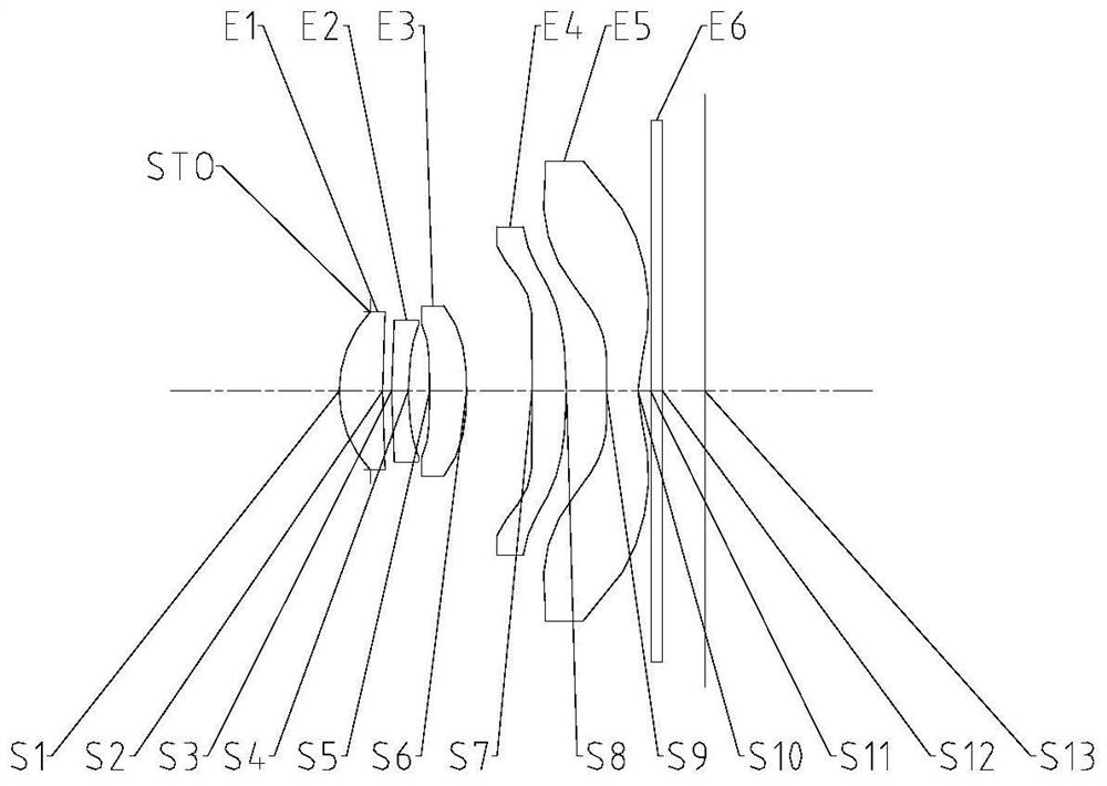
[0049] like Figure 1 to Figure 25 As shown, from the object side to the imaging side, the imaging lens group sequentially includes a first lens with positive refractive power, a second lens with negative refractive power, a third lens with positive refractive power, and a fourth lens with positive refractive power and the fifth lens with negative refractive power; the object side of the first lens is convex, and the imaging side is concave; the object side of the second lens is convex, and the imaging side is concave; the object side of the third lens is concave, and the imaging side is Convex; the object side of the fourth lens is convex, and the imaging side is convex; the object side of the fifth lens is convex, and the imaging side is concave; and at least 3 of the first to fifth lenses are made of glass, and, The axial distance between the object side of the first lens and the imaging surface TTL and the half of the diagonal length of the effective pixel area on the imag...

Embodiment 2

[0063] like Figure 1 to Figure 25 As shown, the imaging lens group sequentially includes from the object side to the imaging side: a first lens with positive refractive power, whose object side is convex, and whose imaging side is concave; a second lens with negative refractive power, whose object side is convex, The imaging side is concave; the third lens with positive power is concave on the object side and the imaging side is convex; the fourth lens with positive power is convex on the object side and the imaging side is convex; with negative power The fifth lens, the object side is convex, and the imaging side is concave; and at least 3 lenses from the first lens to the fifth lens are made of glass, and the Abbe number V1 of the first lens and the A of the third lens The relationship between the shell number V3 and the Abbe number V5 of the fifth lens satisfies: 70<(V1+V3+V5) / 3<85; the air space between the third lens and the fourth lens on the optical axis T34, the fourt...


PUM


Abstract

The invention provides an imaging lens group. The imaging lens group comprises a first lens with positive focal power, the object side surface of the first lens is a convex surface, and the imaging side surface of the first lens is a concave surface; the object side surface of the second lens is a convex surface, and the imaging side surface of the second lens is a concave surface; the object side surface of the third lens is a concave surface, and the imaging side surface of the third lens is a convex surface; the object side surface of the fourth lens is a convex surface, and the imaging side surface of the fourth lens is a convex surface; the object side surface of the fifth lens is a convex surface, and the imaging side surface of the fifth lens is a concave surface; the on-axis distance TTL from the object side surface of the first lens to the imaging surface and the half ImgH of the diagonal length of an effective pixel area on the imaging surface meet the following condition: TTL / ImgHlt; 1.3, 2, 3; the abbe number V1 of the first lens, the abbe number V3 of the third lens and the abbe number V5 of the fifth lens meet the following condition: 70lt; (V1 + V3 + V5) / 3lt; 85). The imaging lens group solves the problem that the imaging lens group in the prior art is difficult to give consideration to large image plane, large aperture and good chromatic aberration at the same time.

Description

technical field [0001] The present invention relates to the technical field of optical imaging equipment, in particular, to an imaging lens group. Background technique [0002] With the continuous development of technology, the competition in the field of mobile phone cameras has become increasingly fierce. Especially in the imaging lens group of high-end flagship models, in addition to the demand for a larger image surface and a larger aperture, mobile phone manufacturers have requirements for the chromatic aberration of the imaging lens group. It is also getting higher and higher. At the same time, it is necessary to ensure good imaging quality. At the same time, it is also necessary that the overall size of the imaging lens group should not be too large, so that it can be applied to ultra-thin electronic products. This is undoubtedly a higher design for the imaging lens group. difficulty challenge. [0003] That is to say, the imaging lens set in the prior art has the pr...

Claims


Application Information

Patent Timeline
Patent Type & Authority Applications(China)
IPC IPC(8): G02B13/00G02B13/18
CPCG02B13/0015G02B13/0045
Inventor 戴付建朱晓晓徐武超赵烈烽
Owner ZHEJIANG SUNNY OPTICAL CO LTD
Why Eureka
Try Eureka