
Meter power supply circuit and use method thereof

A technology for power supply circuits and meters, applied in battery circuit devices, circuit devices, load supply circuits, etc., can solve the problems of low service life of batteries in meters, achieve the effect of improving service life and avoiding large current discharge

Pending Publication Date: 2022-06-07
ZHEJIANG CHINT INSTR & METER
View PDF0 Cites 0 Cited by
  • Summary
  • Abstract
  • Description
  • Claims
  • Application Information

AI Technical Summary

Problems solved by technology

[0005] Therefore, the present invention aims to solve the technical problem of low service life of the battery in the meter, thereby providing a meter power supply circuit and a method for using the same. The technical solution is as follows:

Method used


Image

  • Meter power supply circuit and use method thereof
  • Meter power supply circuit and use method thereof
  • Meter power supply circuit and use method thereof

Examples


Embodiment 1

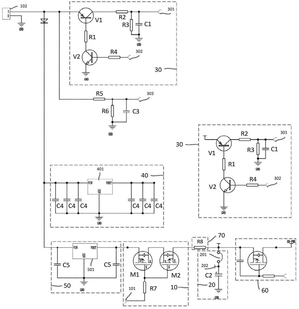
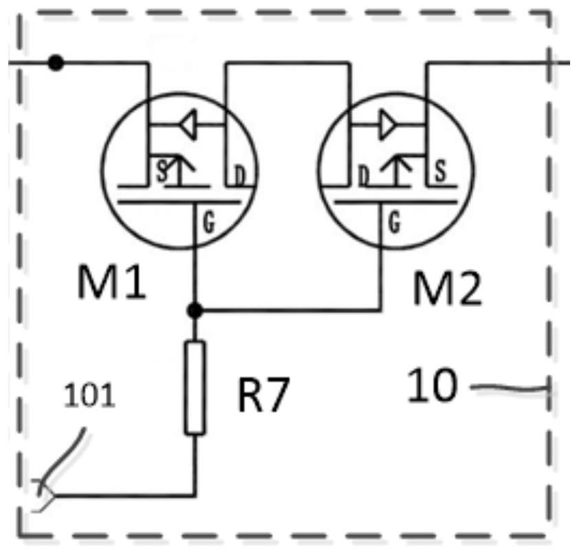
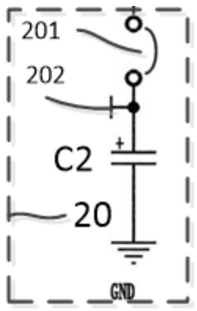
[0029] This embodiment provides a power supply circuit for a meter, and the meter may be a natural gas meter, a water meter, or the like. like Figure 1 to Figure 4 As shown, the meter power supply circuit includes a switch module 10 , a current limiting module 70 and an energy storage module 20 . The first end of the switch module 10 can be connected to the battery 102 , and the second end of the switch module 10 is connected to the input end of the current limiting module 70 . For connection, the output end of the current limiting module 70 can be connected to the power consumption module 60 of the meter. The energy storage module 20 is connected to the output end of the current limiting module 70 and is connected in parallel with the power consumption module 60 of the meter, that is, the energy storage module 20 is connected between the current limiting module 70 and the power consumption module 60 of the meter. The energy storage module 20 can receive current from the bat...

Embodiment 2

[0043] This embodiment provides a method for using a power supply circuit of a meter, Figure 7 It is a flow chart illustrating the operation of the meter power supply circuit provided in Embodiment 1 according to some embodiments of the present invention. Although the processes described below include a number of operations in a particular order, it should be clearly understood that the processes may include more or fewer operations, which may be performed sequentially or in parallel (eg, using parallel processors) or a multithreaded environment). like Figure 7 As shown, the method includes the following steps (S101-S102):

[0044] S101. Use a voltage detection circuit to detect the voltage of the energy storage module.

[0045] like figure 1 , Figure 5 and Image 6 As shown, the voltage detection circuit 30 can detect the voltage of the energy storage module 20 at any time, such as before the power consumption module 60 of the meter is in a working state, or when the...


PUM


Abstract

The invention relates to the field of power supplies, in particular to a meter power supply circuit and a using method thereof, and the power supply circuit comprises a switch module, a first end of which is used for being connected with a battery; the input end of the current-limiting module is connected with the second end of the switch module, and the output end of the current-limiting module is connected with a power consumption module of the meter; the energy storage module is connected between the current limiting module and a power consumption module of the meter and is used for receiving the current from the battery and generating the current; wherein the current provided by the battery to the power consumption module is smaller than the working current of the power consumption module, and the current provided by the energy storage module to the power consumption module is larger than or equal to the working current of the power consumption module. The energy storage module is used for supplying power to the power consumption module, large-current discharging of the battery can be avoided, and therefore the service life of the battery is prolonged.

Description

technical field [0001] The invention relates to the field of power supplies, in particular to a meter power supply circuit and a method of using the same. Background technique [0002] With the continuous development of meters such as gas meters and water meters, the degree of intelligence is getting higher and higher, and more and more functions are integrated. Batteries (such as alkaline batteries or lithium sub-battery, etc.) need to be used to provide electric energy for the meters. . [0003] Alkaline batteries and lithium sub-batteries have high capacity and are widely used in meters. In practical applications, high-power power consumption modules such as communication modules and switch valves in the meter require higher voltage / current to support their work, but batteries often no longer meet the requirements of high-power power consumption modules after a period of operation. voltage / current requirements. [0004] In order to improve the service life of the batte...

Claims


Application Information

Patent Timeline
Patent Type & Authority Applications(China)
IPC IPC(8): H02J7/34H02J7/00G01D11/00
CPCH02J7/34H02J7/0063H02J7/0068H02J7/00304G01D11/00Y02E60/10
Inventor 蒋韦宾曼琳杨金龙张伟郑哲璐王靓钰
Owner ZHEJIANG CHINT INSTR & METER
Learn More