Oil immersion device for rotating shaft production and processing

A technology of oil immersion and rotating shaft, which is applied to the device and coating of the surface coating liquid to achieve the effects of avoiding precipitation, enhancing flow, and enhancing the effect of oil immersion

Active Publication Date: 2022-06-10
DALIAN DEMAISHI PRECISION TECH CO LTD
View PDF7 Cites 0 Cited by
  • Summary
  • Abstract
  • Description
  • Claims
  • Application Information

AI Technical Summary

Problems solved by technology

[0003] The purpose of this invention is to solve the problem of poor oil immersion effect in the prior art, and propose an oil immersion device for shaft production and processing

Method used


Image

  • Oil immersion device for rotating shaft production and processing
  • Oil immersion device for rotating shaft production and processing
  • Oil immersion device for rotating shaft production and processing

Examples


Embodiment 1

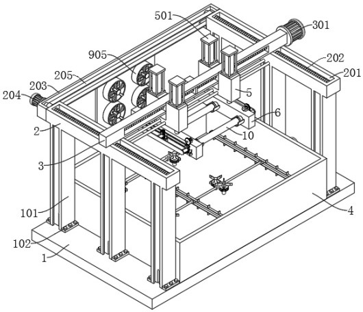
[0044] The vertical board 6 is fixedly connected with a fourth motor 601, the output end of the fourth motor 601 is connected with a driving gear 602, the outer wall of the vertical board 6 is provided with a driven shaft 7, and the outer wall of the driven shaft 7 is fixedly connected with a driving gear 602 The second driven gear 802 meshed with the first driven gear 701 is provided on the threaded sleeve 801 to engage with the first driven gear 701 .

[0045]In this embodiment, after the shaft body 10 is placed on the arc backing plate 603, the auxiliary assembly is controlled to work at this time, and the shaft body 10 is clamped. The specific working process of the auxiliary assembly is: start the fourth motor 601 to drive the The driving gear 602 at the output end rotates, and the driving gear 602 will drive the first driven gear 701 meshed with it to rotate, thereby driving the driven shaft 7 to rotate, and the first driven gear 701 will drive the second driven gear 802 ...

Embodiment 2

[0047] Example 4:

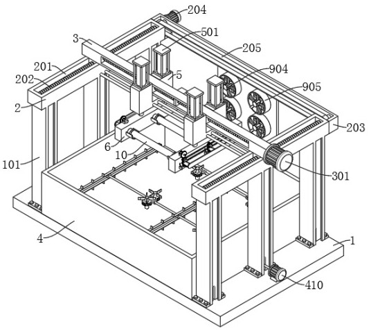
[0048] The outer wall of the rotating shaft 401 is provided with a worm screw 405, the bottom inner wall of the oil immersion tank 4 is provided with a stirring shaft 406, the stirring shaft 406 is provided with a worm wheel 407 meshed with the worm screw 405, the top of the stirring shaft 406 is provided with a rotating plate 408, and the rotating plate The end of 408 away from the stirring shaft 406 is provided with a rubber sheet 409 .

[0049] In this embodiment, when the rotating shaft 4 rotates, it will drive the worm 405 to rotate, and further drive the worm wheel 407 meshed with it to rotate, so that the worm wheel 407 drives the stirring shaft 406 to rotate, so that the rotating plate 408 and the rubber sheet on the stirring shaft 406 Rotate at 409 to stir the liquid, enhance the flow of the liquid, and make the oil immersion effect of the shaft body 10 better.

[0050] Example 5:

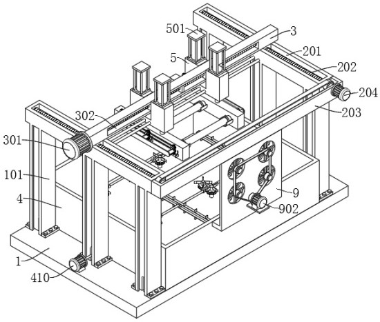
[0051] A vertical plate 9 is provided between the frame plate 20...

Embodiment 3


PUM


Abstract

The invention discloses an oil immersion device for rotating shaft production and processing, and belongs to the field of rotating shaft oil immersion. An oil immersion device for rotating shaft production and machining comprises a bottom plate and further comprises a vertical rod fixedly connected to the top of the bottom plate; the supporting rod is fixedly connected to the top of the vertical rod, and a sliding rod is connected to the supporting rod in a sliding mode; the fixing blocks are slidably connected to the sliding rod, and the bottoms of the two fixing blocks are slidably connected with vertical plates; the arc base plate and the ejector rod are connected to the vertical plate in a sliding mode, and an auxiliary assembly is arranged on the vertical plate; the shaft body is arranged on the arc base plate; the oil immersion tank corresponds to the shaft body and is fixedly connected to the outer wall of the top of the bottom plate; compared with the prior art, oil immersion operation can be facilitated, meanwhile, flowing of oil liquid is enhanced, the contact area between the shaft body and other components is small, the oil immersion effect is better, the corrosion resistance of the shaft body is further enhanced, and the service life of the shaft body is prolonged.

Description

technical field [0001] The invention relates to the technical field of oil immersion of rotating shafts, in particular to an oil immersion device for production and processing of rotating shafts. Background technique [0002] The shaft is one of the main parts of the machine. It is generally a metal round rod. Wheels and other rotating parts revolve around it or rotate with it. During the production process of the shaft, the shaft needs to be treated with oil to improve its resistance Corrosion, which greatly increases the service life of the later period, but now the staff put the rotating shaft into the basket and put it into the oil storage shell to soak it in oil, but there will be friction between each rotating shaft and between the rotating shaft and the basket There is contact, thereby affecting the flushability of its immersion oil, reducing the effect and work efficiency of immersion oil, and making it inconvenient for people to use. Therefore, we propose an oil imm...

Claims


Application Information

Patent Timeline
Patent Type & Authority Applications(China)
IPC IPC(8): B05C3/09B05C3/04B05C13/02
CPCB05C3/09B05C3/04B05C13/02
Inventor 何建平
Owner DALIAN DEMAISHI PRECISION TECH CO LTD
Why Eureka
Try Eureka