Three-dimensional UV printing equipment for manufacturing artistic well lid with colored patterns on surface and implementation method of three-dimensional UV printing equipment

A color pattern, printing equipment technology, applied in printing devices, mechanical equipment, printing and other directions, can solve the problems of affecting the printing quality, hindered use, poor lubricity of the connection between the moving block and the screw rod, etc., to ensure production efficiency and ensure printing. Quality, stable moving effect

Pending Publication Date: 2022-06-17
盐城高科道路设施有限公司
View PDF1 Cites 0 Cited by
  • Summary
  • Abstract
  • Description
  • Claims
  • Application Information

AI Technical Summary

Problems solved by technology

[0003] The existing technology has the following problems: 1. The existing three-dimensional UV printing equipment cannot adjust and fix the manhole cover when it is in use, which affects the printing quality; 2.

Method used


Image

  • Three-dimensional UV printing equipment for manufacturing artistic well lid with colored patterns on surface and implementation method of three-dimensional UV printing equipment
  • Three-dimensional UV printing equipment for manufacturing artistic well lid with colored patterns on surface and implementation method of three-dimensional UV printing equipment
  • Three-dimensional UV printing equipment for manufacturing artistic well lid with colored patterns on surface and implementation method of three-dimensional UV printing equipment

Examples


Example Embodiment

[0024]实施例1

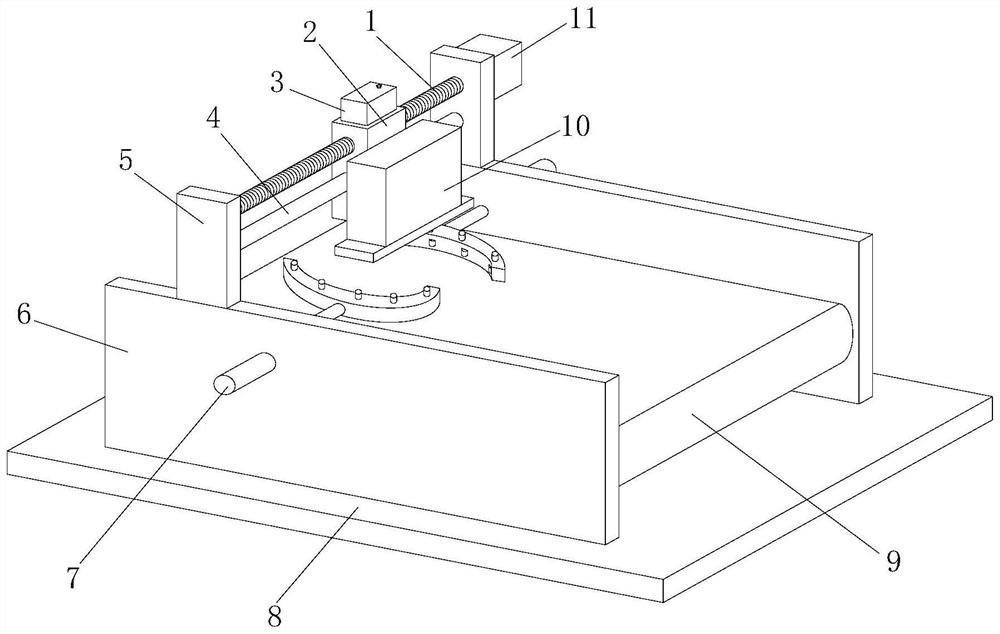
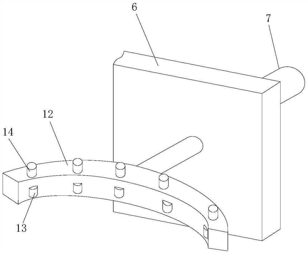
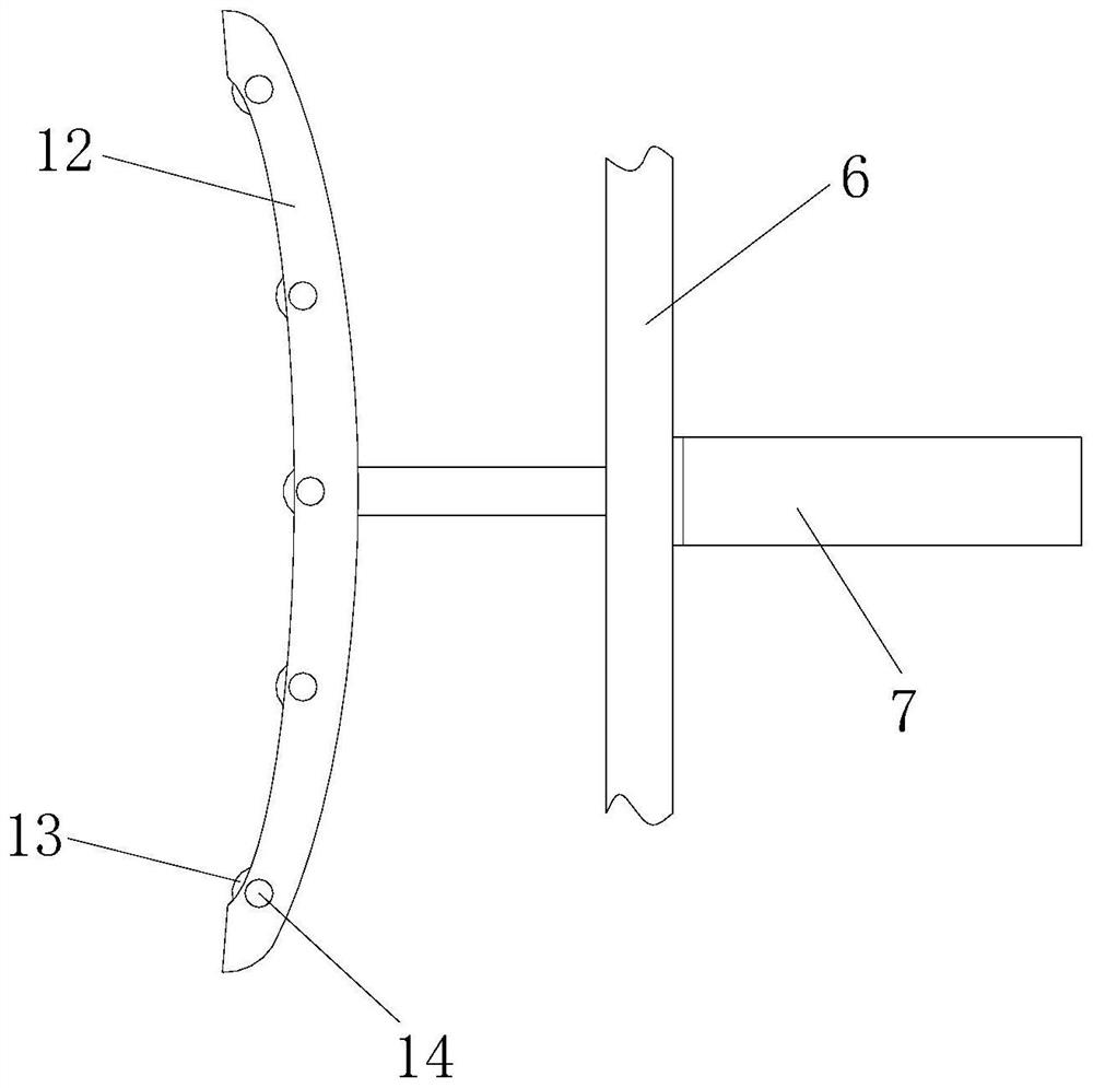
[0025]请参阅图1-5,本发明提供以下技术方案:一种表面彩色图案艺术井盖制作立体UV打印设备,包括底座8,底座8的上端两侧设置有立架6,立架6的中间设置有输送带9,立架6的上端设置有安装架5,两个安装架5的中间设置有丝杆1,丝杆1的下方设置有滑动杆4,安装架5的侧边与丝杆1对应位置设置有步进电机11,丝杆1和滑动杆4的表面设置有移动块2,移动块2的表面设置有打印机构10,打印机构10的下端设置有喷头组件21,立架6的侧边设置有伸缩气缸7,伸缩气缸7的活塞杆连接有弧形架12,弧形架12的弧形内壁均设置有转动轮13,弧形架12的上端设置有微型电机14。

[0026]本发明中进一步的,转动轮13与弧形架12的凹槽之间轴承转动连接,微型电机14的转轴与转动轮13键销连接固定,

[0027]通过采用上述技术方案,保证微型电机14带动转动轮13稳定转动。

[0028]本实施例使用时,将待打印的井盖放置输送带9上,输送至喷头组件21下端停止,伸缩气缸7伸长带动弧形架12移动,使转动轮13贴近井盖侧边,微型电机14转动带动转动轮13旋转,转动轮13带动井盖旋转,使井盖进行位置调节,伸缩气缸7伸长使弧形架12侧边的转动轮13夹紧井盖,避免移动;步进电机11转动带动丝杆1旋转,丝杆1所在的移动块2移动,移动块2侧边的打印机构10移动,打印机构10下端的喷头组件21对准井盖进行表面彩色图案制作;

Example Embodiment

[0029]实施例2

[0030]本实施例与实施例1不同之处在于:底座8的上端侧边设置有驱动电机20,驱动电机20的转轴设置有主动锥齿轮19,立架6的侧边设置有固定架16,固定架16的中间设置有螺杆17,螺杆17的两端均设置有传动锥齿轮18,输送带9的转轴设置有从动锥齿轮15,

[0031]本发明中进一步的,从动锥齿轮15与传动锥齿轮18啮合传动,主动锥齿轮19与传动锥齿轮18啮合传动,螺杆17与固定架16轴承转动连接,

[0032]通过采用上述技术方案,保证各锥齿轮之间稳定传动。

[0033]本实施例使用时,驱动电机20转动带动主动锥齿轮19旋转,主动锥齿轮19带动传动锥齿轮18旋转,通过螺杆17传动,使螺杆17上端的传动锥齿轮18带动从动锥齿轮15旋转,从动锥齿轮15带动输送带9旋转,输送带9将井盖输送至喷头组件21下端;

Example Embodiment

[0034]实施例3

[0035]本实施例与实施例1和实施例2不同之处在于:移动块2的上端设置有输油组件3,输油组件3包括注油口31、盛放箱32、输送管33和输送泵35,其中,移动块2的上端设置有盛放箱32,盛放箱32的上端一侧设置有注油口31,盛放箱32的上端另一侧设置有输送管33,输送管33的另一端连接有输送泵35,移动块2的内部设置有输油孔22,输送泵35的出液口与输油孔22之间设置有连接管,

[0036]通过采用上述技术方案,输送泵35工作,通过输送管33从盛放箱32内抽取润滑液,然后输送至输油孔22,然后流到移动块2内丝杆1的表面,使移动块2与丝杆1连接处润滑,稳定移动。

[0037]本发明中进一步的,输油孔22的下端与移动块2的螺孔对应,

[0038]通过采用上述技术方案,润滑油通过输油孔22流到移动块2内丝杆1的表面。

[0039]本发明中进一步的,移动块2的上端位于盛放箱32和输送泵35的外表面设置有外保护壳34,

[0040]通过采用上述技术方案,提高对盛放箱32和输送泵35的保护。

[0041]本发明中进一步的,表面彩色图案艺术井盖制作立体UV打印设备的实现方法如下:

[0042]①将待打印的井盖放置输送带9上,驱动电机20转动带动主动锥齿轮19旋转,主动锥齿轮19带动传动锥齿轮18旋转,通过螺杆17传动,使螺杆17上端的传动锥齿轮18带动从动锥齿轮15旋转,从动锥齿轮15带动输送带9旋转,输送带9将井盖输送至喷头组件21下端;

[0043]②伸缩气缸7伸长带动弧形架12移动,使转动轮13贴近井盖侧边,微型电机14转动带动转动轮13旋转,转动轮13带动井盖旋转,使井盖进行位置调节,伸缩气缸7伸长使弧形架12侧边的转动轮13夹紧井盖,避免移动;

[0044]③步进电机11转动带动丝杆1旋转,丝杆1所在的移动块2移动,移动块2侧边的打印机构10移动,打印机构10下端的喷头组件21对准井盖进行表面彩色图案制作;

[0045]④输送泵35工作,通过输送管33从盛放箱32内抽取润滑液,然后输送至输油孔22,然后流到移动块2内丝杆1的表面,使移动块2与丝杆1连接处润滑,稳定移动,


PUM


Abstract

The invention discloses three-dimensional UV printing equipment for manufacturing an artistic well lid with colored patterns on the surface and an implementation method of the three-dimensional UV printing equipment, and belongs to the technical field of printing equipment.The three-dimensional UV printing equipment comprises a base, vertical frames are arranged on the two sides of the upper end of the base, a conveying belt is arranged in the middles of the vertical frames, and mounting frames are arranged at the upper ends of the vertical frames; a telescopic air cylinder extends to drive an arc-shaped frame to move, a rotating wheel is made to be close to the side edge of a well lid, a micro motor rotates to drive the rotating wheel to rotate, the rotating wheel drives the well lid to rotate, the position of the well lid is adjusted, the telescopic air cylinder extends to enable the rotating wheel on the side edge of the arc-shaped frame to clamp the well lid, and movement is avoided; the printing quality is ensured; the driving motor rotates to drive the driving bevel gear to rotate, the driving bevel gear drives the transmission bevel gear to rotate, the transmission bevel gear at the upper end of the screw drives the driven bevel gear to rotate through transmission of the screw, the driven bevel gear drives the conveying belt to rotate, stable transmission is guaranteed, and production efficiency is guaranteed.

Description

technical field [0001] The invention belongs to the technical field of printing equipment, and in particular relates to a three-dimensional UV printing equipment for making artistic manhole covers with surface color patterns and a realization method thereof. Background technique [0002] UV printer is a high-tech plate-free full-color digital printing machine, which is not limited by materials. [1] It can be printed on T-shirts, sliding doors, cabinet doors, sliding doors, glass, plates, various signs, crystal, PVC, acrylic, metal, plastic, stone, leather and other surfaces. No need for plate making, one-time printing, beautiful and rich colors, wear resistance, UV protection, simple and convenient operation, fast printing image speed, fully in line with industrial printing standards. [0003] The existing technology has the following problems: 1. The existing three-dimensional UV printing equipment cannot adjust and fix the manhole cover when it is in use, which affects th...

Claims


Application Information

Patent Timeline
IPC IPC(8): B41J3/407B41J2/01B41J11/00F16N7/38
CPCB41J3/407B41J2/01B41J11/00F16N7/38
Inventor 郑竹茂郑进铭
Owner 盐城高科道路设施有限公司
Why Eureka
Try Eureka