
Copper wire unwinding system for winding transformer coil and use method

A transformer coil and copper wire technology, which is applied in the manufacture of inductors/transformers/magnets, electrical components, circuits, etc., can solve the problems of insufficient tension of copper wires, affecting the performance of transformers, and insufficient coil fit, so as to ensure the winding quality , Guaranteed performance and quality, and the effect of eliminating bending stress

Pending Publication Date: 2022-06-17
宜昌楚能变压器有限公司
View PDF0 Cites 0 Cited by
  • Summary
  • Abstract
  • Description
  • Claims
  • Application Information

AI Technical Summary

Problems solved by technology

[0003] In the above-mentioned copper wire winding process, there is insufficient tension of the copper wire, which leads to the loose winding of the copper wire on the iron core, which affects the performan

Method used


Image

  • Copper wire unwinding system for winding transformer coil and use method
  • Copper wire unwinding system for winding transformer coil and use method
  • Copper wire unwinding system for winding transformer coil and use method

Examples


Example Embodiment

[0044]实施例1:

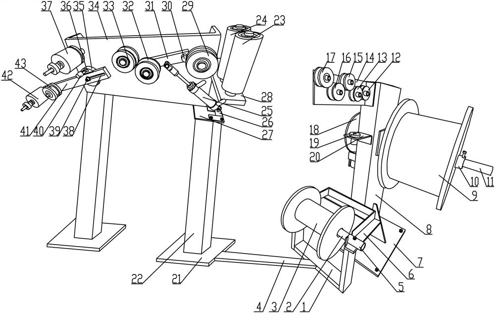
[0045]参见图1-6,变压器线圈绕制的铜线放卷系统,它包括用于对不同型号铜线卷进行存放的存放料架结构;存放料架结构包括用于存放小卷铜线的小卷存放架结构和用于存放大卷的大卷存放架结构;存放料架结构通过能够拆卸的连接板4与脚板21固定相连,脚板21的顶部固定有支撑柱22,支撑柱22的顶部固定有导向架板34,导向架板34的进线侧设置有竖向进线辊机构;导向架板34的外壁上安装有第一导向轮29和第二导向轮33,在第一导向轮29和第二导向轮33之间的部位设置有气动张紧调节机构;导向架板34的出线侧设置有末级槽轮37,末级槽轮37的正下方设置有手动张力调节组件。此铜线放卷系统能够用于变压器生产过程中,铁芯绕线的铜线放卷作业,进而保证了放卷过程中,能够对铜线进行有效的张力调节,使其精密的缠绕在铁芯上;而且在放卷过程中,能够在一定程度上消除其弯曲应力,保证了后续缠绕过程中铜线之间的贴合度,最终保证铁芯性能和质量。具体使用过程中,通过

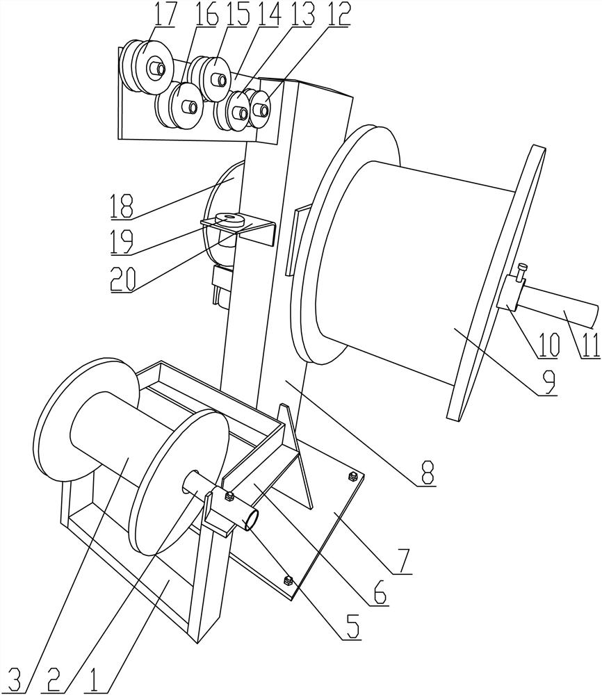
[0046]进一步的,所述大卷存放架结构包括第一底板7,第一底板7的顶部固定有第一立柱8,第一立柱8的上部侧壁上安装有第一卷轴11,第一卷轴11上通过挡环10限位支撑有大铜线卷9;第一卷轴11的另一端固定安装有控制其转动速度的刹车盘18。通过上述的大卷存放架结构能够用于存放大卷的铜线卷。具体存放过程中,通过将大铜线卷9存放在第一卷轴11上,然后在放卷过程中,通过大铜线卷9的转动实现放卷。

[0047]进一步的,所述小卷存放架结构包括U型支架1,U型支架1的顶部固定有卷筒支架6,卷筒支架6上固定有卷轴筒5,卷轴筒5的内部转动支撑有第二卷轴2,第二卷轴2上限位支撑有小铜线卷3。通过上述的小卷存放架结构能够用于存放小卷的铜线卷。具体存放过程中,通过将小铜线卷3存放在第二卷轴2上,然后在放卷过程中,通过小铜线卷3的转动实现放卷。

[0048]进一步的,所述大卷存放架结构的第一立柱8上安装有用于消除弯曲铜线应力的应力消除装置;所述应力消除装置包括固定在第一立柱8的顶部前侧壁上的滚轮板14,滚轮板14上平行安装有第一槽轮12、第二槽轮13和第三槽轮16;第二槽轮13和第三槽轮16的上方之间安装有第四槽轮15,第三槽轮16的末端上方布置安装有第五槽轮17。通过上述的应力消除装置能够用于消除铜线上的应力,进而保证其后续缠绕的紧密度。具体绕线过程...

Example Embodiment

[0053]实施例2:

[0054]变压器线圈绕制的铜线放卷系统的使用方法,包括以下步骤:

[0055]步骤一,根据所需要绕制的铜线卷的尺寸型号,选择相应的存放料架结构,并将需要放线的大铜线卷9或小铜线卷3安装在存放料架结构上;

[0056]步骤二,将铜线的引线端穿过第一立柱8上的应力消除装置;

[0057]步骤三,再将铜线穿过竖向进线辊机构之后再引入到第一导向轮29、气动张紧调节机构和第二导向轮33;

[0058]步骤四,再将铜线绕过末级槽轮37和手动张力调节组件之后初步缠绕在铁芯上;

[0059]步骤五,启动绕线机,驱动铁芯转动,进而将铜线绕制在铁芯上。

Example Embodiment

[0060]实施例3:

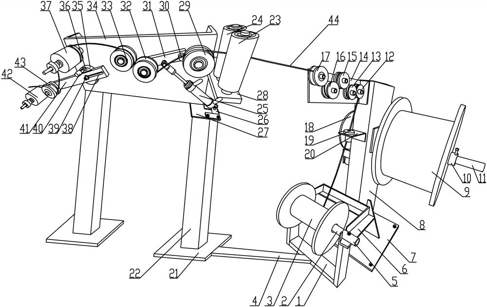
[0061]所述步骤二中铜线在应力消除装置上的具体绕线方法为,通过将铜线44穿过导向套19之后,先绕过第一槽轮12的顶部,再绕过第二槽轮13的底部,再绕过第四槽轮15的顶部,再绕过第三槽轮16的底部,再绕过第五槽轮17的顶部;

[0062]所述步骤四中铜线具体绕线方法为,通过将铜线44绕过第一导向轮29的顶部,再绕过第一张紧轮32的底部,再绕过第二导向轮33的顶部,再绕过末级槽轮37之后绕过压线轮43的底部,再绕过末级滚轮42的顶部;

[0063]铜线具体张紧力调节过程为,当需要对张力调节时,启动气缸25,通过气缸25驱动转动臂31,通过转动臂31带动第一张紧轮32,通过第一张紧轮32压紧铜线44;

[0064]通过调节转动块35的安装角度,进而调节滑动杆41的安装角度,并沿着铰接螺栓39滑动滑动杆41,进而调节滑动杆41的伸出长度,进而调节压线轮43和末级滚轮42的位置来调节铜线的张紧程度。


PUM


Abstract

The invention provides a copper wire unwinding system for transformer coil winding and a using method. A storage rack structure is fixedly connected with a foot plate through a detachable connecting plate, a supporting column is fixed to the top of the foot plate, a guide frame plate is fixed to the top of the supporting column, and a vertical wire inlet roller mechanism is arranged on the wire inlet side of the guide frame plate; a first guide wheel and a second guide wheel are installed on the outer wall of the guide frame plate, and a pneumatic tensioning adjusting mechanism is arranged between the first guide wheel and the second guide wheel. A final-stage grooved wheel is arranged on the wire outlet side of the guide frame plate, and a manual tension adjusting assembly is arranged under the final-stage grooved wheel. The copper wire unwinding system can be used for the copper wire unwinding operation of iron core winding in the transformer production process, so that it is guaranteed that the tension of the copper wire can be effectively adjusted in the unwinding process, and finally the performance and quality of an iron core are guaranteed.

Description

technical field [0001] The invention belongs to the field of transformer production equipment, in particular to a copper wire unwinding system and a use method for winding transformer coils. Background technique [0002] In the automatic production process of transformer coils, the copper wire needs to be wound on the iron core. In the process of winding the copper wire, the basic process adopted is: first, the copper wire coil is stored on the material rack, and then the The end of the copper wire is connected to the iron core to be wound, and finally, the iron core is driven to rotate, and then the copper wire is pulled to be wound on the iron core. [0003] In the above-mentioned copper wire winding process, there is insufficient tension of the copper wire, which leads to the loose winding of the copper wire on the iron core, which affects the performance of the transformer; in addition, due to the thicker diameter of the copper wire, when it is pulled from the After unw...

Claims


Application Information

Patent Timeline
IPC IPC(8): H01F41/094
CPCH01F41/094
Inventor 吕月军刘明黄志张长斌李祖红
Owner 宜昌楚能变压器有限公司
Learn More