
Flexible display panel and manufacturing method therefor

a flexible display and manufacturing method technology, applied in the field of display devices, can solve the problems of poor signal transmission, affecting the normal display of the flexible display product, affecting the cracking of wires, so as to prolong the service life of the display product, increase the flexibility, and reduce the stress of metal wires.

Pending Publication Date: 2022-02-03
WUHAN CHINA STAR OPTOELECTRONICS SEMICON DISPLAY TECH CO LTD
View PDF2 Cites 1 Cited by
  • Summary
  • Abstract
  • Description
  • Claims
  • Application Information

AI Technical Summary

Benefits of technology

The present disclosure provides a flexible display panel that has reduced stress of metal wires in the bending region, increasing its flexibility and prolonging the service life of the display products. The panel includes an organic insulating layer and a metal layer arranged on the organic insulating layer, with protrusions in the organic insulating layer of the bending region that can release stress to reduce bending cracks of the metal wires. This results in a narrower border and increased service life of the display panel device. A manufacturing method is also provided to make the flexible display panel.

Problems solved by technology

Although breakthrough progress has been made in terms of flexible technology, there are a number of challenges.
As the bending degree gradually increases, the metal lead wires in the bending region is easily cracked due to the stress in a vertical direction perpendicular to the bending region, thereby causing poor signal transmission and affecting normal display of the flexible display product.
If the bending occurs in an area of the wires arrangement, the high-strength stretching can cause the wires to crack and influence the service life of the display products.
Therefore, there is a need for a method to reduce stress of the bending region wire, thereby increasing its flexibility and prolonging the service life of the display products.

Method used


Image

  • Flexible display panel and manufacturing method therefor
  • Flexible display panel and manufacturing method therefor
  • Flexible display panel and manufacturing method therefor

Examples


Embodiment Construction

[0047]The following embodiments refer to the accompanying figures for exemplifying specific implementable embodiments of the present disclosure in a suitable environment.

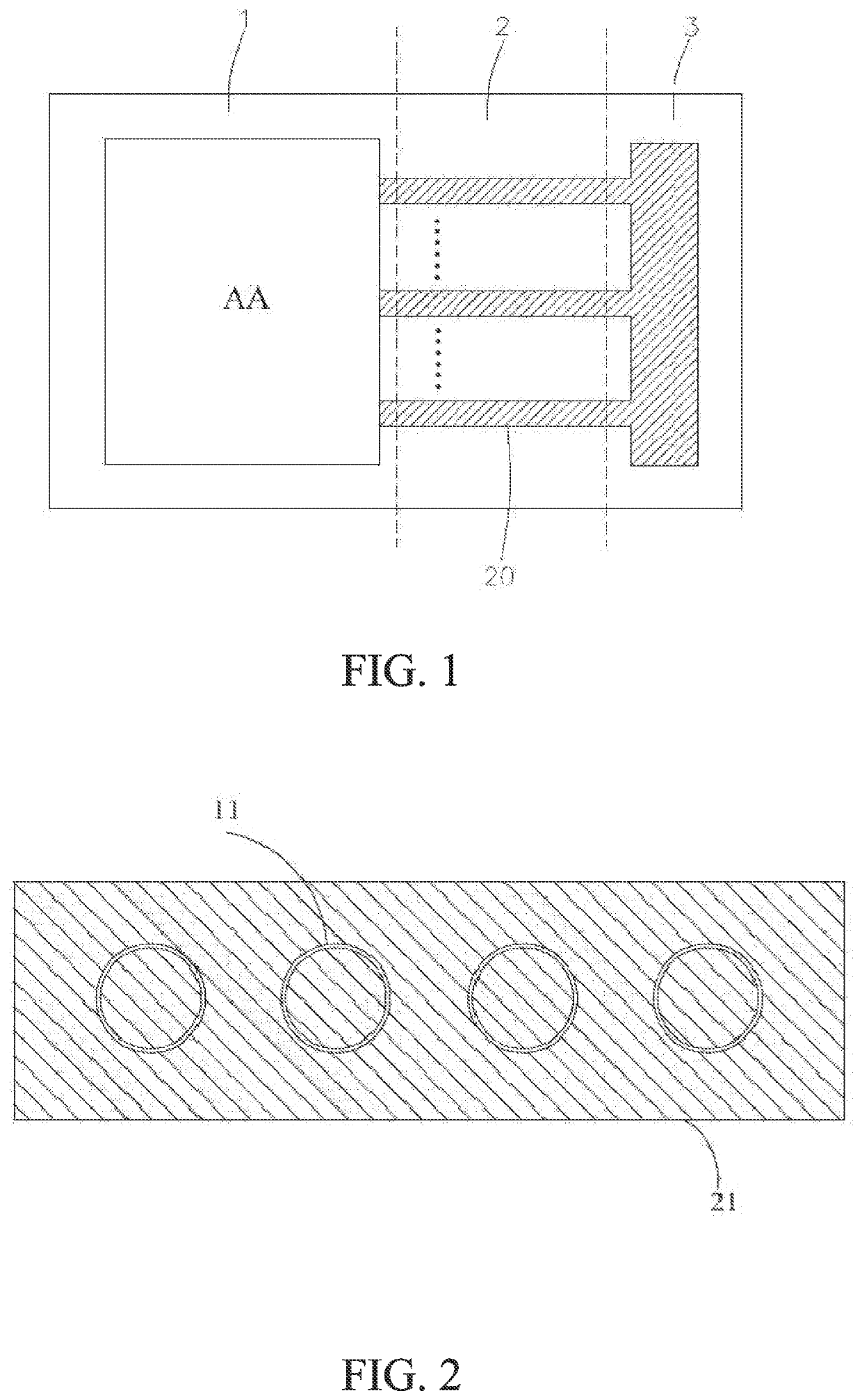
[0048]Referring to FIGS. 1-3, a first embodiment of the present disclosure provides a flexible display panel that is divided into a display region 1 located in the middle region, a binding region 3 located on an outer side of the display region 1, and a bending region 2 located between the display region 1 and the binding region 3. The flexible display panel includes an organic insulating layer 10 and a metal layer 20 arranged on the organic insulating layer 10.

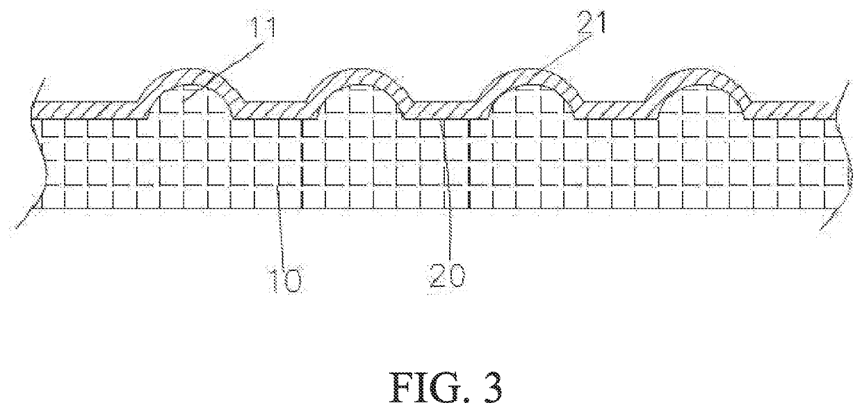
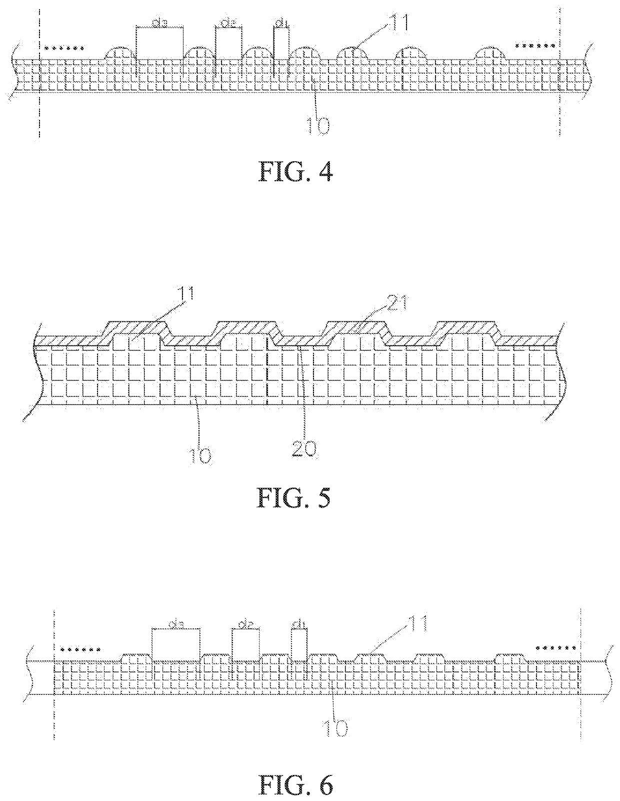
[0049]In an embodiment, a plurality of protrusions 11 are arranged in the organic insulating layer 10 of the bending region 2, such that a surface of the organic insulating layer 10 includes concave and convex shapes in the bending region 2.

[0050]In an embodiment, the metal layer 20 includes a plurality of metal wires 21 that pass through the bending region 2...


PUM

PropertyMeasurementUnit
structureaaaaaaaaaa
densityaaaaaaaaaa
shapeaaaaaaaaaa

Abstract

A flexible display panel and a manufacturing method therefor. The flexible display panel comprises an organic insulating layer and a metal layer disposed on the organic insulating layer, and is divided into a display region located in the middle, a binding region located outside the display region, and a bending region located between the display region and the binding region. The organic insulating layer is provided with a plurality of protrusions in the bending region so that the surface of the organic insulating layer is uneven in the bending region. The metal layer comprises a plurality of metal wires penetrating the bending region, and each metal wire covers a part the protrusions of the organic insulating so that the surface the metal wire is also uneven along with the organic insulating layer. During the bending of the flexible display panel, the protrusions would release part of stress.

Description

BACKGROUNDField[0001]The present disclosure relates to a technical field of display devices, and more particularly to a flexible display panel and manufacturing method therefor.Background[0002]A flexible display is a deformable and bendable display device. The bending function of the display screen do not affect the display function of the display screen. Compared with a traditional hard display screen, the flexible display screen has advantages of light, small size, better flexibility, low power consumption, and the like. The flexible display screen can be designed as electronic products with various properties, such as curved televisions, curled electronic watches, flexible mobile phones, and the like. Although breakthrough progress has been made in terms of flexible technology, there are a number of challenges.[0003]The narrow border of the display device, even without the border, is the mainstream development trend of the current display technology. For the flexible display prod...

Claims


Application Information

Patent Timeline
Patent Type & Authority Applications(United States)
IPC IPC(8): G09F9/30G03F7/00
CPCG09F9/301G03F7/0007G09G3/32G09G3/035G09G2300/0426
Inventor PENG, SIMINJIN, JIANGJIANG
Owner WUHAN CHINA STAR OPTOELECTRONICS SEMICON DISPLAY TECH CO LTD
Learn More