High-rotating-speed detachable bearing for electric fan

An electric fan, high-speed technology, applied in the field of bearings for electric fans, can solve problems such as increasing bearing wear, and achieve the effect of reducing wear

Pending Publication Date: 2022-06-21
黄奎
View PDF0 Cites 1 Cited by
  • Summary
  • Abstract
  • Description
  • Claims
  • Application Information

AI Technical Summary

Problems solved by technology

[0004] In order to overcome the disadvantages of the existing fan bearings that due to the high-speed rotation of the ball and the friction of the inner ring, the ball will further rub against the inner ring due to thermal expansion and increase the wear of the bearing. Bearings for high-speed detachable electric fans with long bearing life

Method used


Image

  • High-rotating-speed detachable bearing for electric fan
  • High-rotating-speed detachable bearing for electric fan
  • High-rotating-speed detachable bearing for electric fan

Examples


Embodiment 1

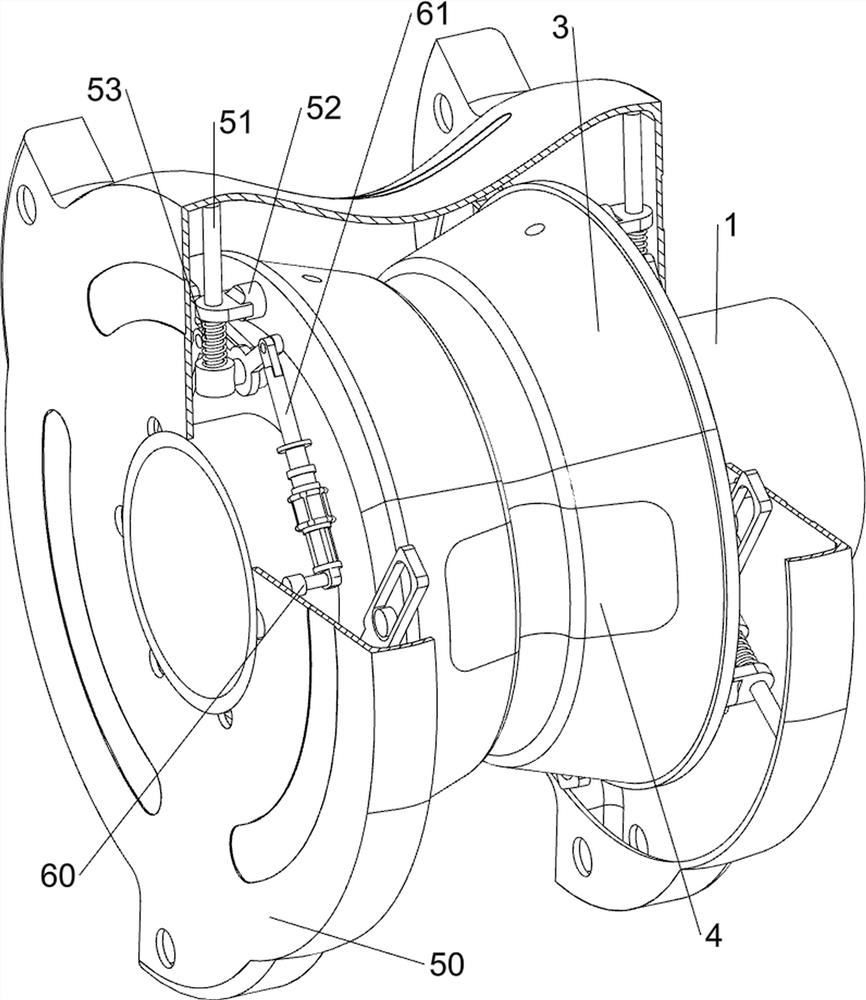
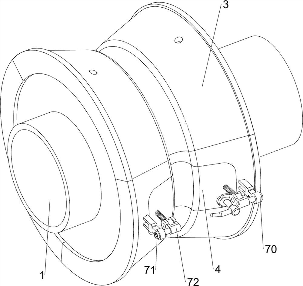
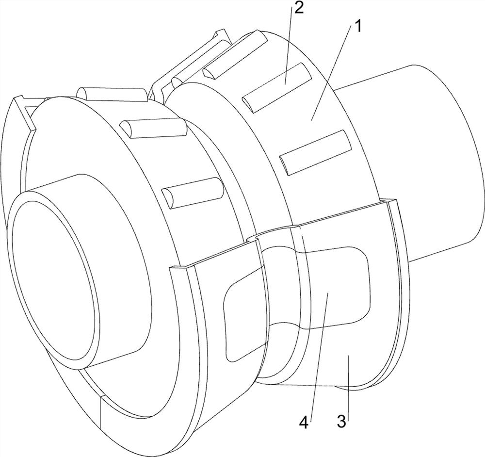
[0034] When using the device, the staff installs the device on the electric fan for use. When the fan blade rotates, the roller 1 rotates in the limit ring 3. Under the action of the ball 2, the distance between the roller 1 and the limit ring can be reduced. The frictional force between the positioning rings 3 enables the roller shaft 1 to rotate at a high speed. While the roller shaft 1 is rotating at a high speed, it will press the positioning ring 3 through the ball 2 to expand outwards. Under the action of the expansion mechanism 5, It can buffer the impact force of the limit ring 3 and reduce the wear of the limit ring 3 and the ball 2. At the same time, it can also keep the limit ring 3 in contact with the ball 2, thereby adjusting the pretightening force of the bearing. When individual balls 2 need to be disassembled, the staff opens the closing plate 4 for disassembly and replacement. When all the balls 2 need to be disassembled, the staff opens the limit ring 3 outwar...

Embodiment 2

[0041] like figure 2 , Figure 9 and Figure 10 As shown, a lubricating mechanism 8 is also included. The lubricating mechanism 8 adds lubricating oil to the roller 1 and the ball 2. The lubricating mechanism 8 includes a feeding tube 80, a retaining cylinder 81 and a connecting spring 83. The left and right sides of the upper part of the protective shell 50 All are welded with a blanking tube 80, the lower part of the blanking tube 80 penetrates into the uppermost limit block, and three retaining tubes 81 are slidably arranged on the blanking tube 80, and a limiting groove 82 is opened on the retaining tube 81. Limiting slots 82 are all slidably connected with adjacent feeding pipes 80, and the uppermost limiting block moves upwards with retaining cylinder 81, and connecting spring 83 is connected between retaining cylinder 81 and the adjacent discharging pipe 80. The upper part of the pipe 80 is provided with six feeding troughs 84, and the top of the retaining cylinder 8...


PUM


Abstract

The invention relates to a bearing for an electric fan, in particular to a high-rotating-speed detachable bearing for an electric fan. The high-rotating-speed detachable bearing for the electric fan can reduce bearing abrasion and prolong the service life of the fan bearing. A high-rotating-speed detachable bearing for an electric fan comprises a rolling shaft, balls, a limiting ring, a closing plate and the like. A circle of detachable balls are symmetrically arranged on the left side and the right side of the rolling shaft respectively, a limiting ring is rotationally arranged on the rolling shaft and composed of three limiting blocks capable of being separated, and a detachable closing plate is arranged on the limiting block on the foremost side. The rolling shaft extrudes the limiting ring to expand outwards through the balls while rotating at a high speed, under the action of the sliding blocks and the reset springs, impact force borne by the limiting ring can be buffered, abrasion of the limiting ring and the balls is reduced, meanwhile, the limiting ring can be kept in the state of being in contact with the balls, and therefore the pre-tightening force of the bearing is adjusted.

Description

technical field [0001] The invention relates to a bearing for an electric fan, in particular to a high-speed detachable bearing for an electric fan. Background technique [0002] The main function of the bearing is to reduce the friction coefficient during the rotation of the mechanical rotating body. The common bearings mainly include sliding bearings, joint bearings, deep groove ball bearings, ball bearings, etc. The rotation of electric fans mainly depends on the function of bearings. Ordinary electric fans mainly use oil bearings and ball bearings. Oil bearings are sleeve bearings that use sliding friction. The friction is reduced by lubricating oil, but this kind of bearings are severely worn during use. , the service life is short, while the ball bearing adopts rolling friction, which can effectively reduce the friction between the bearing surfaces and improve the service life of the fan bearing. However, when the ball bearing is in use, due to the high-speed rotation ...

Claims


Application Information

Patent Timeline
Patent Type & Authority Applications(China)
IPC IPC(8): F04D29/056F04D29/059F04D29/063F04D29/64
CPCF04D29/056F04D29/059F04D29/063F04D29/646
Inventor 黄奎
Owner 黄奎
Why Eureka
Try Eureka