
Signal transmission system

A signal transmission system and signal value technology, applied in the field of signal transmission systems, can solve the problems of low reliability, electromagnetic interference, no consideration of complete replacement of signal transmission systems, and high cost.

Pending Publication Date: 2022-06-21
工具制造有限责任公司
View PDF8 Cites 0 Cited by
  • Summary
  • Abstract
  • Description
  • Claims
  • Application Information

AI Technical Summary

Problems solved by technology

[0006] Even though the transmission of measured values ​​by means of applied current has proven valuable over the years due to its reliability and its extremely low susceptibility to electromagnetic disturbances, it brings with it the following disadvantages: In addition to the actual measured values ​​and the above-mentioned Beyond the two error states, it is almost impossible to transmit other information
Although this solution can be implemented without problems when constructing new installations, in the case of existing installations all components need to be replaced, i.e. all measuring sensors, control and evaluation units and especially all wiring, which brings not only high costly and often require long interruptions to ongoing processes
Therefore, a complete replacement of the signal transmission system is usually not considered in the case of existing installations

Method used


Image

  • Signal transmission system
  • Signal transmission system

Examples


Embodiment Construction

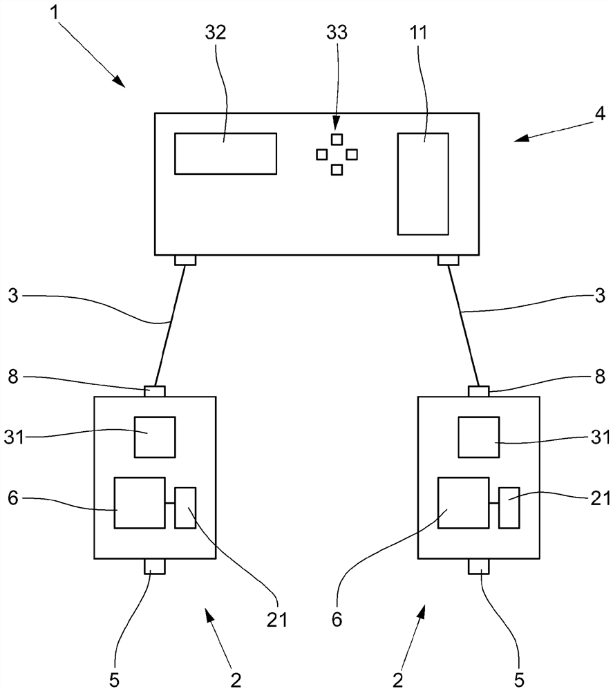
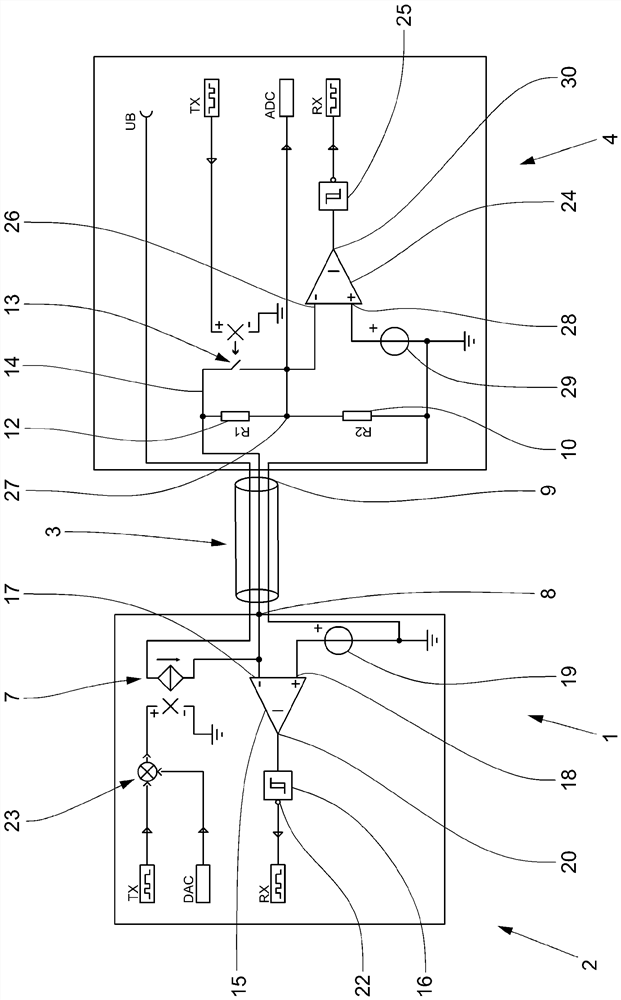
[0029] from figure 2 It can be seen in the simplified circuit diagram of the signal transmission system 1 shown that the current source 7 in the measured value generator 2 is connected via the output connection 8 to a core wire of the line 3, that is, the above-mentioned third core wire, via which The core wire carries an applied DC current representing the measured value. At the other end of the line 3 the core is connected to the signal input 9 of the control and evaluation unit 4 . The control and evaluation unit 4 has a load 10 which is connected to the signal input 9 such that the current transmitted via the third core of the line 3 flows through the load 10 . By means of an A / D converter in the microprocessor 11, the voltage dropped across the load 10 can be detected and evaluated.

[0030] In the signal transmission system 1 according to the invention or the control and evaluation unit 4 according to the invention, electrical components are provided in addition to th...


PUM


Abstract

The invention relates to a signal transmission system, comprising at least one signal value generator having an electronic unit and a current source, the signal value generator feeding an applied current in a range between a predetermined first value and a predetermined second value into the line, a line, and a control and evaluation unit having a load and a microprocessor, the voltage dropped across the load or the current flowing through the load is detected and evaluated in a control and evaluation unit. The load is connected in series in the control and evaluation unit with at least one electrical component on which a DC voltage drop occurs when a current flows through the electrical component, and the at least one electrical component can be selectively bridged by means of a switch, and the microprocessor compares the voltage U1 dropped across the load when the electrical component is bridged or the current flowing through the load with the voltage U2 dropped across the load when the electrical component is connected in series with the load or the current flowing through the load, and identifies an error when a threshold value is exceeded or below.

Description

technical field [0001] The invention relates to a signal transmission system with at least one signal value generator, a circuit and a control and evaluation unit, wherein the signal value generator has an electronic unit and a current source and switches between a predetermined first value and a predetermined second An applied current between two values, in particular in the range between 4 mA and 20 mA, is fed into the line. The control and evaluation unit has a load and a microprocessor and detects the voltage drop across the load. Furthermore, the invention relates to a measured value generator and an evaluation unit for a corresponding signal transmission system. Background technique [0002] Signal transmission systems are used in particular in process control and plant technology to transmit process values ​​from various locations to mostly central monitoring and control locations. For this purpose, corresponding signal value generators are located on site, for exam...

Claims


Application Information

Patent Timeline
Patent Type & Authority Applications(China)
IPC IPC(8): G08C19/00
CPCG08C19/00
Inventor H-J·许布纳F·贝特格E·布克
Owner 工具制造有限责任公司
Learn More