
Broadband response element applied to rail train

A broadband response, rail train technology, applied in electrical components, railway car body parts, piezoelectric effect/electrostrictive or magnetostrictive motors, etc. Low energy efficiency and other problems, to achieve the effect of widening the operating frequency width, stable energy harvesting conversion, and improving energy harvesting conversion efficiency

Active Publication Date: 2022-06-21
SHANGHAI UNIV OF ENG SCI
View PDF5 Cites 0 Cited by
  • Summary
  • Abstract
  • Description
  • Claims
  • Application Information

AI Technical Summary

Problems solved by technology

The traditional power supply methods mainly include two types: wired sensor and battery power supply. The wired power supply line is complicated, installation and operation and maintenance are difficult, and the technical transformation cost of old cars is extremely high. Although battery power supply can solve the passive problem, the cost High, and will cause environmental damage, there are safety hazards, which is not conducive to the use of long battery life
[0003]The passive wireless sensor can convert the energy existing in the environment, without the need for battery replacement, the battery life is stronger, and under the operating conditions of urban rail transit vehicles, vibration Impact is the most common form of energy. It is the energy basis for converting vibration energy in the environment into electrical energy for power supply using piezoelectric energy collection technology. Piezoelectric beam cantilever beam is one of the most commonly used structures, with simple structure and high power density. Advantages, but in practical applications, the environmental energy is not continuously and evenly distributed, and it has the characteristics of fluctuation, instability, and frequency dispersion, which leads to low energy collection efficiency of passive sensors, and there is a risk of insufficient power supply and detection interruption

Method used


Image

  • Broadband response element applied to rail train
  • Broadband response element applied to rail train
  • Broadband response element applied to rail train

Examples


Embodiment Construction

[0018] In order to make the purposes, technical solutions and advantages of the embodiments of the present invention clearer, the technical solutions in the embodiments of the present invention will be clearly and completely described below with reference to the accompanying drawings in the embodiments of the present invention. Obviously, the described embodiments These are some embodiments of the present invention, but not all embodiments. Based on the embodiments of the present invention, all other embodiments obtained by those of ordinary skill in the art without creative efforts shall fall within the protection scope of the present invention.

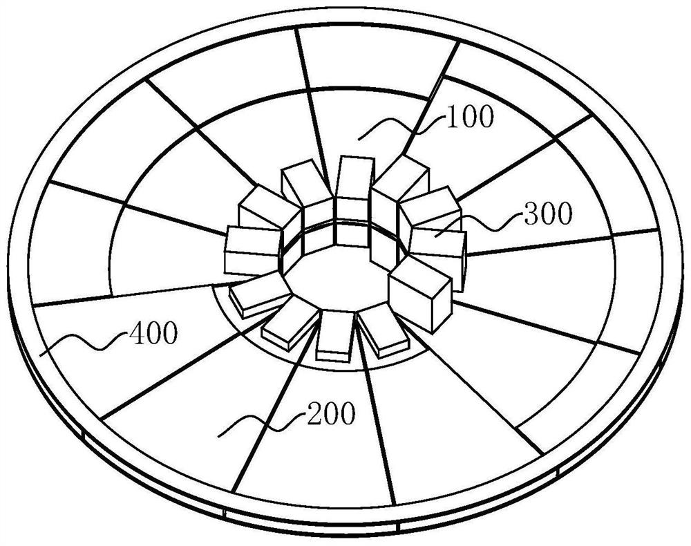
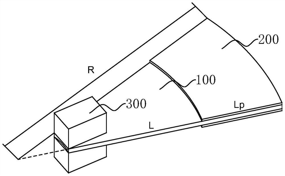
[0019] like figure 1 As shown, in one embodiment, a broadband response element applied to a rail train includes a metal base 100, a mass 300 and a piezoelectric ceramic 200; the metal base 100 is arranged in a fan ring structure, and the piezoelectric ceramic 200 is attached to the On both sides of the metal base 100, a plurality o...


PUM


Abstract

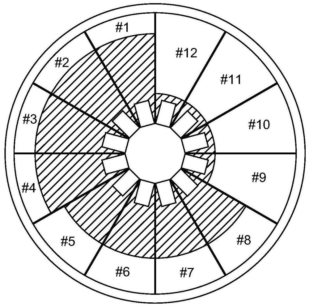
The invention relates to a broadband response element applied to a rail train. The broadband response element comprises a metal substrate, a mass block and piezoelectric ceramics, the metal substrates are arranged in a sector ring structure, the piezoelectric ceramics are attached to the two faces of the metal substrates, the multiple metal substrates are arrayed in the circumferential direction to form a disc structure, the outer edge of the disc structure is clamped and fixed through a circular ring, and the multiple mass blocks are fixed to the two faces of the metal substrates at the inner edge of the disc structure respectively. According to the broadband response element applied to the rail train, the fan-shaped cantilever beams are arranged in the circumferential direction in an array mode, vibration energy in the vibration environment of the rail train can be collected through adjustment of element parameters on the fan-shaped cantilever beams, the working frequency width can be effectively widened, the energy collection and conversion efficiency can be improved, and energy collection and conversion are more stable.

Description

technical field [0001] The invention relates to the technical field of vibration energy conversion of rail trains, in particular to a broadband response element applied to rail trains. Background technique [0002] In recent years, with the rapid development of my country's rail transit industry, rail transit has gradually developed in the direction of energy saving and intelligent operation and maintenance. With the development of microelectronic technology and wireless technology, passive, low-carbon and intelligent small sensors be realized. Due to the complex operation state and large operation volume of my country's rail transit system, the requirements for sensor power supply are correspondingly increased. The traditional power supply methods mainly include two types: wired sensor and battery power supply. The wired power supply circuit is complicated, and the installation and operation and maintenance are difficult. The technical transformation cost of the old car is ...

Claims


Application Information

Patent Timeline
Patent Type & Authority Applications(China)
IPC IPC(8): H02N2/18B61D43/00
CPCH02N2/186B61D43/00
Inventor 郑树彬钟倩文彭乐乐李立明周炯丁亚琦陈亚荣孙佳慧
Owner SHANGHAI UNIV OF ENG SCI
Learn More