
Blood collection needle capable of controlling flow through switch structure and blood collection tube

A technology for controlling flow and switching structure, applied in the field of medical devices, can solve the problems that the collection personnel cannot accurately control the blood volume collected by the blood collection tube, affect the accurate detection of blood by the testing personnel, and the collection of low or excessive blood volume. Blood collection work, avoid excessive collection, increase the effect of stability

Inactive Publication Date: 2022-06-24
QINGDAO BLOOD CENT
View PDF0 Cites 0 Cited by
  • Summary
  • Abstract
  • Description
  • Claims
  • Application Information

AI Technical Summary

Problems solved by technology

[0003] Vacuum blood collection tubes use the negative pressure inside the blood collection tubes to achieve the power of patients to draw blood. However, when using blood collection tubes and blood collection to collect blood from patients, the collectors cannot accurately control the amount of blood collected by the blood collection tubes, and generally rely on the staff In this process, the blood volume inside the blood collection tube is sometimes collected too low or too much, which affects the precise detection of blood by the test personnel. Therefore, we provide a blood collection needle that controls the flow through the switch structure and blood collection tubes to solve the above problems

Method used


Image

  • Blood collection needle capable of controlling flow through switch structure and blood collection tube
  • Blood collection needle capable of controlling flow through switch structure and blood collection tube
  • Blood collection needle capable of controlling flow through switch structure and blood collection tube

Examples


Embodiment Construction

[0026] The technical solutions in the embodiments of the present invention will be clearly and completely described below with reference to the accompanying drawings in the embodiments of the present invention. Obviously, the described embodiments are only a part of the embodiments of the present invention, but not all of the embodiments. Based on the embodiments of the present invention, all other embodiments obtained by those of ordinary skill in the art without creative efforts shall fall within the protection scope of the present invention.

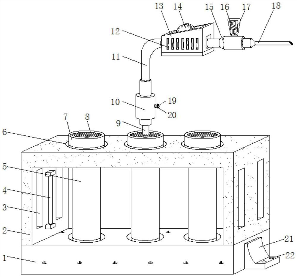
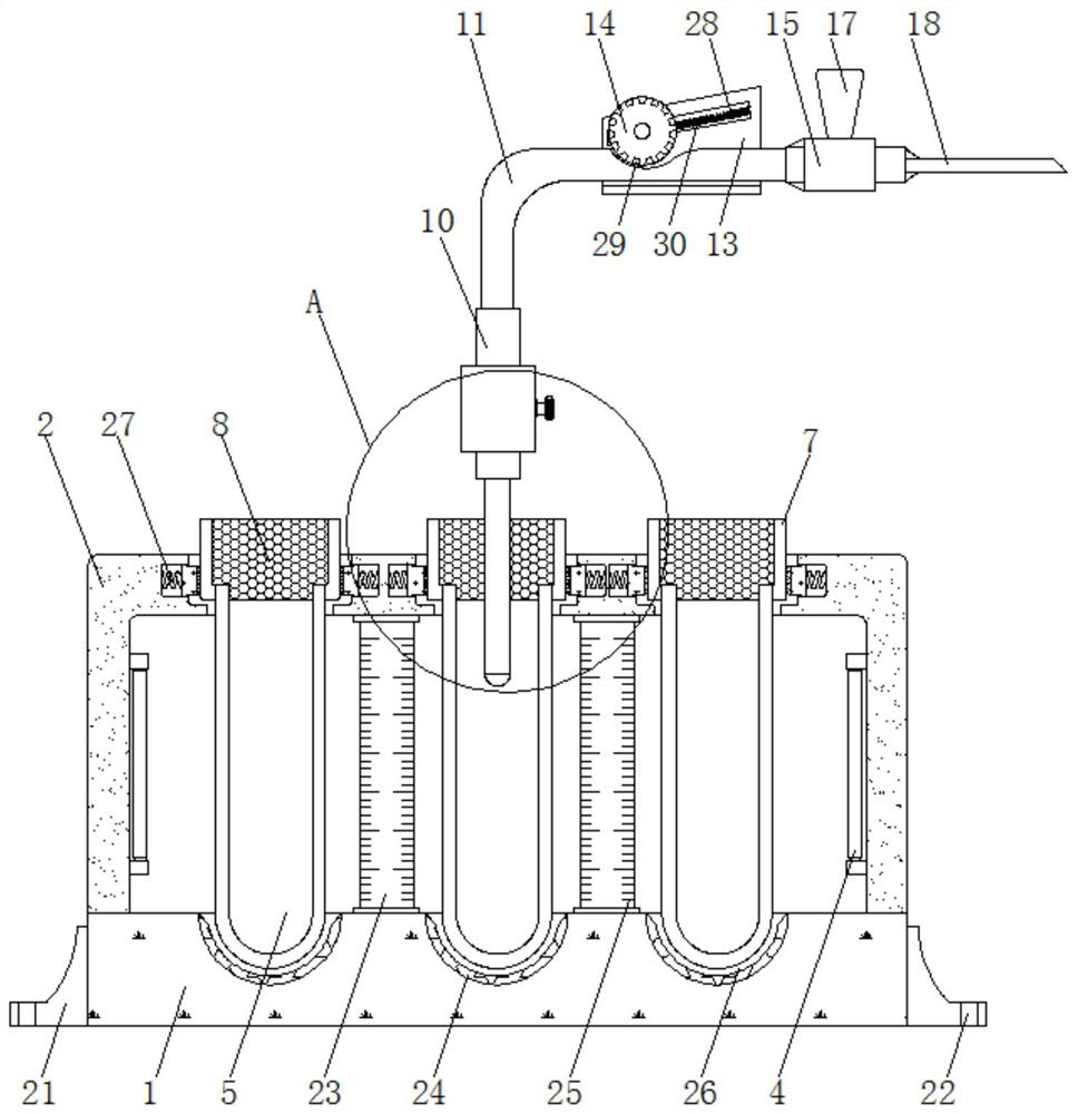
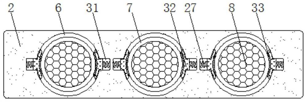
[0027] The present invention provides such as Figure 1-7 The illustrated blood collection needle and blood collection tube that control flow through a switch structure include a placement plate 1, the upper surface of the placement plate 1 is fixedly connected with a support frame 2, and the upper surface of the support frame 2 is provided with a set of clamping holes 6, each A vacuum blood collection tube 5 is clamped to the inner w...


PUM


Abstract

The blood taking needle and the blood taking tube capable of controlling the flow through the switch structure comprise a placing plate, a supporting frame is fixedly connected to the upper surface of the placing plate, a set of clamping holes are formed in the upper surface of the supporting frame, and a vacuum blood taking tube is clamped to the inner wall of each clamping hole. The top end of each vacuum blood collection tube is fixedly connected with a protective sleeve head. The blood taking needle and the blood taking tube capable of controlling the flow through the switch structure comprise a placement plate, a first connector, a spherical cavity, a sealing ball plug, a through hole rotating shaft and a rotating wheel are arranged, the rotating wheel can be rotated to drive the rotating shaft to rotate, then the sealing ball plug is driven to rotate in the spherical cavity, a through hole is made to rotate, and adjustment of the opening of the through hole is completed; according to the vacuum blood collection tube, the secondary flow limiting work effect of blood collection is achieved, the blood flow speed during blood collection is effectively controlled, through cooperation with the scale paste, stable and accurate blood collection of workers is achieved, the situation that the collection amount of the vacuum blood collection tube is too large is avoided, and blood detection work is facilitated.

Description

technical field [0001] The invention relates to the technical field of medical devices, in particular to a blood collection needle and blood collection tube whose flow is controlled by a switch structure. Background technique [0002] Medical devices refer to instruments, equipment, appliances, in vitro diagnostic reagents and calibrators, materials, and other similar or related items that are directly or indirectly used in the human body. Medical devices include medical equipment and medical consumables, of which vacuum blood collection tubes and blood collection needles are Medical devices are often used in the blood collection department, and the existing blood collection tubes and blood collection needles still have certain deficiencies in their use. [0003] The vacuum blood collection tube uses the negative pressure inside the blood collection tube to realize the power when the patient draws blood. However, when the existing blood collection tube and blood collection a...

Claims


Application Information

Patent Timeline
Patent Type & Authority Applications(China)
IPC IPC(8): A61B5/153
CPCA61B5/15003A61B5/150221A61B5/150946A61B5/153
Inventor 何丽芹
Owner QINGDAO BLOOD CENT
Learn More