
Direct-current excitation magnetic separator capable of adjusting magnetism and speed

A DC excitation and magnetic separator technology, applied in the field of magnetic separators, can solve the problems of high cost, inability to adjust the magnetic position and speed, and need to be magnetized, and achieves the effect of reducing the cost and avoiding non-magnetic weakening.

Active Publication Date: 2022-06-24
包头市颐能电气修建有限责任公司
View PDF10 Cites 0 Cited by
  • Summary
  • Abstract
  • Description
  • Claims
  • Application Information

AI Technical Summary

Problems solved by technology

[0004] In order to make up for the above deficiencies, the present invention provides a DC excitation adjustable magnetic speed-adjustable magnetic separator, which aims to improve the existing magnetic separators that are expensive, cannot adjust the magnetic position speed, and need to be magnetized after long-term use. question

Method used


Image

  • Direct-current excitation magnetic separator capable of adjusting magnetism and speed
  • Direct-current excitation magnetic separator capable of adjusting magnetism and speed
  • Direct-current excitation magnetic separator capable of adjusting magnetism and speed

Examples


Embodiment

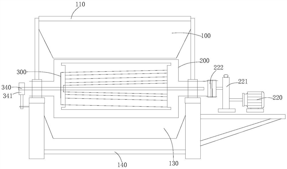
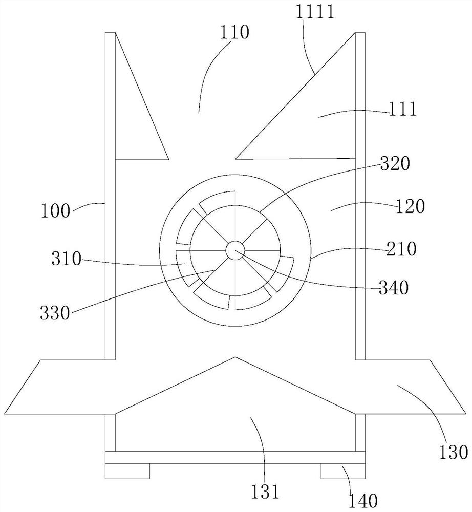
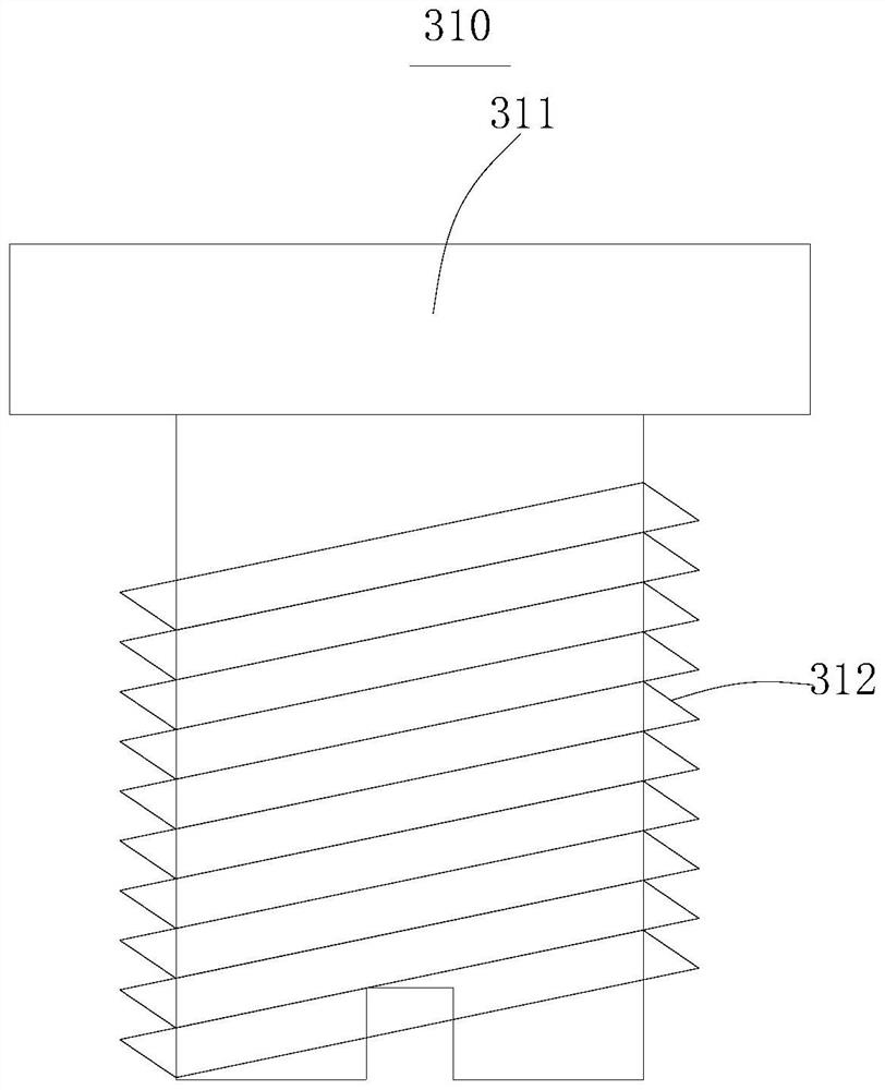
[0037] see figure 1 , the present invention provides a technical solution: a DC excitation adjustable magnetic speed-regulating magnetic separator, comprising a material distribution box 100 , a rotating assembly 200 and an excitation assembly 300 .

[0038] Among them, see figure 1 , the rotating component 200 and the excitation component 300 are installed on the material distribution box 100, the material distribution box 100 is used for receiving materials, and the rotating component 200 cooperates with the excitation component 300 to separate the magnetically conductive material and the non-magnetically conductive material in the material.

[0039] see figure 1 and figure 2, the material distribution box 100 has a feeding port 110, a material distribution cavity 120 and two discharge ports 130 that communicate with each other, wherein, the feeding port 110 has a guide block 111, specifically, the guide block 111 has a guide slope 1111, the guide slope The 1111 can guid...

no. 2 example

[0045] Based on the adjusting member 341 provided in the first embodiment of the present application, the second embodiment of the present application provides another adjusting member 341 . The adjusting member 341 in the first embodiment is only a preferred mode of the first embodiment, and the implementation of the second embodiment will not affect the independent implementation of the first embodiment.

[0046] The second embodiment of the present application will be further described below with reference to the accompanying drawings and embodiments.

[0047] see figure 1 and Figure 7 Specifically, the adjustment bolt seat 3413 is directly fixed on the support frame 140, and the adjustment rod 3411 is hinged on the support frame 140 through the rotating shaft. When the magnetic position needs to be adjusted, the bolt on the adjustment bolt seat 3413 is rotated, and the bolt is pressed against the One end of the adjustment rod 3411 rotates around its axis of rotation, an...


PUM


Abstract

The invention provides a direct-current excitation magnetic separator capable of adjusting magnetism and speed, which belongs to the technical field of magnetic separators and comprises a material distribution box, a rotating assembly and an excitation assembly. The material distributing box is provided with a feeding port, a material distributing cavity and two discharging ports which are communicated with one another, the feeding port is provided with a guide block, a material distributing partition plate is arranged between the two discharging ports, the material distributing partition plate has a gradient gradually inclining outwards from the center, the rotating assembly comprises a rotating cylinder and a driving part connected with the rotating cylinder, the rotating cylinder is arranged in the material distributing cavity, and the driving part is connected with the driving part. The driving part can drive the rotating cylinder to rotate in the material distributing cavity, the excitation assembly is movably arranged in the rotating cylinder, the excitation assembly is provided with a magnetic attraction area and a non-magnetic area, and when the rotating cylinder rotates, raw materials fed from the feeding port can be separated conveniently. The equipment is high in manufacturing cost, can adjust the magnetic potential rotating speed, and does not need to be magnetized after being used for a long time.

Description

technical field [0001] The invention relates to the technical field of magnetic separators, in particular to a DC excitation adjustable magnetic speed-regulating magnetic separator. Background technique [0002] There are a small amount of iron powder, iron particles, etc. in the iron ore raw materials and the slag slag of iron smelting. In order to effectively separate and avoid the waste of resources, it is necessary to use a magnetic separator for magnetic separation operations. [0003] However, the existing magnetic separators for the separation of magnetic materials and non-magnetic materials still have the following shortcomings: 1. The magnetic separation magnetic field adopts rare earth permanent magnets, which are expensive to manufacture; 2. The magnetic position and rotational speed cannot be adjusted; 3. Long Magnetization is required after time of use. SUMMARY OF THE INVENTION [0004] In order to make up for the above deficiencies, the present invention pro...

Claims


Application Information

Patent Timeline
Patent Type & Authority Applications(China)
IPC IPC(8): B03C1/12
CPCB03C1/12Y02W30/62
Inventor 刘俊平李俊青苏金
Owner 包头市颐能电气修建有限责任公司
Learn More