Eureka AIR delivers breakthrough ideas for toughest innovation challenges, trusted by R&D personnel around the world.

Pattern sewing machine

A technology of pattern sewing machine and sewing machine head, which is applied in the field of sewing machines, can solve the problems of high preparation cost, bulky size, and invariability, and achieve the effect of dense stitches, low preparation cost, and increased offset speed

Pending Publication Date: 2022-06-24
赣州飞越智能科技有限公司
View PDF0 Cites 0 Cited by
  • Summary
  • Abstract
  • Description
  • Claims
  • Application Information

AI Technical Summary

Problems solved by technology

This electronic pattern sewing machine has the disadvantages of bulky size and high preparation cost, and a programming input is required every time a specific style of pattern sewing is performed, and the use is very invariable.

Method used


Image

  • Pattern sewing machine
  • Pattern sewing machine
  • Pattern sewing machine

Examples


Embodiment 1

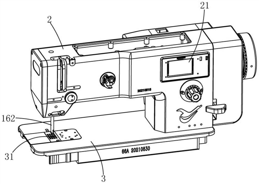
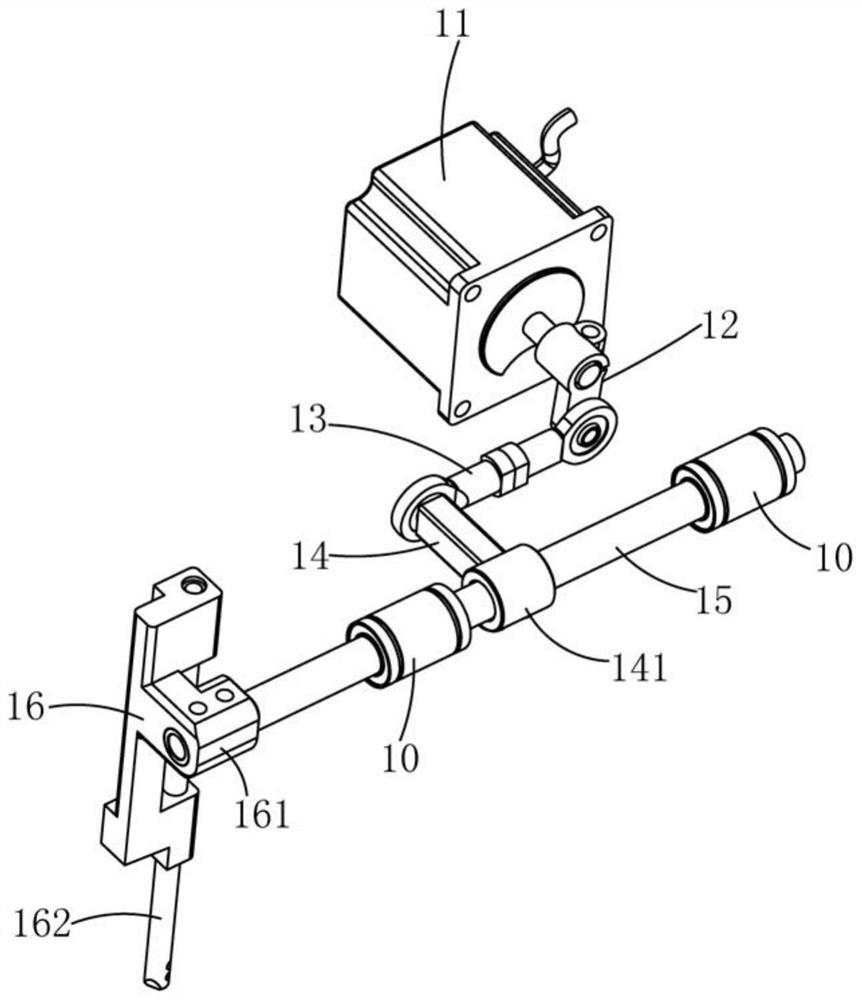
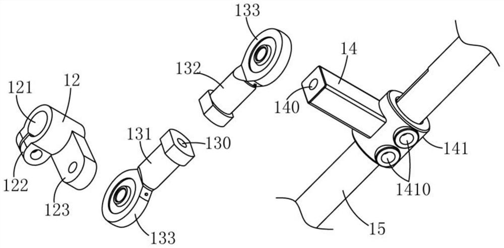
[0027] A pattern sewing machine such as Figure 1 to Figure 3 As shown, it includes a control device 21, a sewing platform 3 and a sewing machine head 2 fixed on the surface of the sewing platform 3. The sewing platform 3 is provided with a supporting base plate 31, and the supporting base plate 31 is provided with a longitudinal feeding mechanism. The inside of the sewing machine head 2 There is a needle frame 16 for assembling threading needles, the needle frame 16 is located directly above the support base plate 31, the needle frame 16 is movable along the horizontal direction, and the needle frame 16 is connected with a bias drive mechanism, a bias drive mechanism and a longitudinal feeding mechanism The control device 21 is electrically connected respectively; wherein, the bias drive mechanism includes a bias drive motor 11 and a connecting rod structure, and the connecting rod structure includes a swing rod 12, a first connecting rod 13, a second connecting rod 14 and a t...

Embodiment 2

[0039] like Figure 8 As shown, the structure of the pattern sewing machine shown in this embodiment is basically the same as that shown in Embodiment 1, the difference is that the top of the needle frame 16 in this embodiment is pivotally connected to the sewing machine head 2, and the needle The frame 16 is installed on the sewing machine head 2 in a swinging state, and the needle frame 16 is driven by the biasing drive mechanism to make a swing offset at a set angle, so as to complete the transformation of different threading positions, so as to realize the above-mentioned sewing pattern 1, sewing pattern 2 and others. Sewing pattern; wherein, the bias drive mechanism includes a swing rod 12, an extension rod 61 and a swing link 6, the first end of the swing rod 12 is fixed to the output shaft of the bias drive motor 11, and the other end of the swing rod 12 It is fixedly connected with the first end of the extension rod 61, and the swing rod 12 and the extension rod 61 are...


PUM


Abstract

The invention discloses a pattern sewing machine which comprises a control device, a sewing platform and a sewing machine head fixed to the surface of the sewing platform, the sewing platform is provided with a material supporting base plate, the material supporting base plate is provided with a longitudinal feeding mechanism, a needle frame used for assembling a threading needle is arranged in the sewing machine head, and the needle frame is located over the material supporting base plate. The needle frames are connected with each other and are movably arranged; the needle frame is connected with a deviation driving mechanism, the deviation driving mechanism comprises a deviation driving motor and a connecting rod structure, the deviation driving motor is in transmission connection with the needle frame through the connecting rod structure, and the deviation driving motor and the longitudinal feeding mechanism are electrically connected with the control device so as to achieve continuous conversion of the needle feeding position of the threading needle and pattern stitches. Compared with the prior art, two-shaft type pattern sewing is achieved through the control of the motor capable of controlling the rotation angle and the connecting rod structure, the structure is simple, the manufacturing cost is low, and operation is stable and reliable.

Description

technical field [0001] The invention relates to the technical field of sewing machines, in particular to a pattern sewing machine. Background technique [0002] A sewing machine is a machine that uses one or more sewing threads to form one or more stitches on the sewing material to interweave or sew one or more layers of sewing material. The sewing machine can sew fabrics such as cotton, fiber crops, silk, wool, and artificial fibers, and products such as leather, plastics, and paper. The lockstitch, the most common, consists of two stitches that are interwoven like twisted rope, with the interweaving point in the middle of the sewing material. From the cross-section of the stitches, the two stitches are like two locks locking each other, so they are called lock stitches. This kind of stitching is used in sewing materials such as cotton, wool fabric or leather with a small shrinkage rate. The front and back sides have the same shape, just like a dotted line. The stitches a...

Claims


Application Information

Patent Timeline
Patent Type & Authority Applications(China)
IPC IPC(8): D05B9/00D05B55/14D05B35/00D05B69/02
CPCD05B9/00D05B55/14D05B35/00D05B69/02
Inventor 肖修锋南永淑
Owner 赣州飞越智能科技有限公司
Why Eureka
Eureka Blog
Learn More