High-protection interlocking self-compensation isolating switch

An isolation switch and high protection technology, applied in the direction of electric switches, air switch parts, electrical components, etc., can solve the problems of rapid wear of static contacts, elastic compensation, and wrong operating status of products, so as to ensure safety and prevent corrosion , to ensure the effect of flexibility

Pending Publication Date: 2022-06-24
XIANYANG YAHUA ELECTRONIC APPLIANCE CO LTD
View PDF0 Cites 0 Cited by
  • Summary
  • Abstract
  • Description
  • Claims
  • Application Information

AI Technical Summary

Problems solved by technology

[0004] 1. When the moving contact and the static contact are closed, the contact area is guaranteed by the elasticity of the static contact itself. However, under the condition of excessive contact pressure, the static contact is easy to cause rapid wear, because its own elasticity cannot be compensated, so The contact area and contact pressure will be reduced accordingly; if the use time is longer or the operation frequency is higher, it will often cause poor contact of the contacts, which will cause safety accidents;
[0005] 2. There is no protection requirement for the installation panel. When the external environment is harsh, rainwater and dust will often enter the product and cause abnormal contact of the contacts, thus causing safety accidents;
[0006] 3. The movement of the handle is unrestricted. When the product is manually operated by non-operators, it is easy to cause errors in the operating status of the product, thus causing safety accidents

Method used


Image

  • High-protection interlocking self-compensation isolating switch
  • High-protection interlocking self-compensation isolating switch
  • High-protection interlocking self-compensation isolating switch

Examples


Embodiment Construction

[0031] In order to make the purposes, technical solutions and advantages of the embodiments of the present invention clearer, the technical solutions in the embodiments of the present invention will be clearly and completely described below with reference to the accompanying drawings in the embodiments of the present invention. Obviously, the described embodiments These are some embodiments of the present invention, but not all embodiments. Based on the embodiments of the present invention, all other embodiments obtained by those of ordinary skill in the art without creative work fall within the protection scope of the present invention.

[0032] Below in conjunction with accompanying drawing, the present invention is described in further detail:

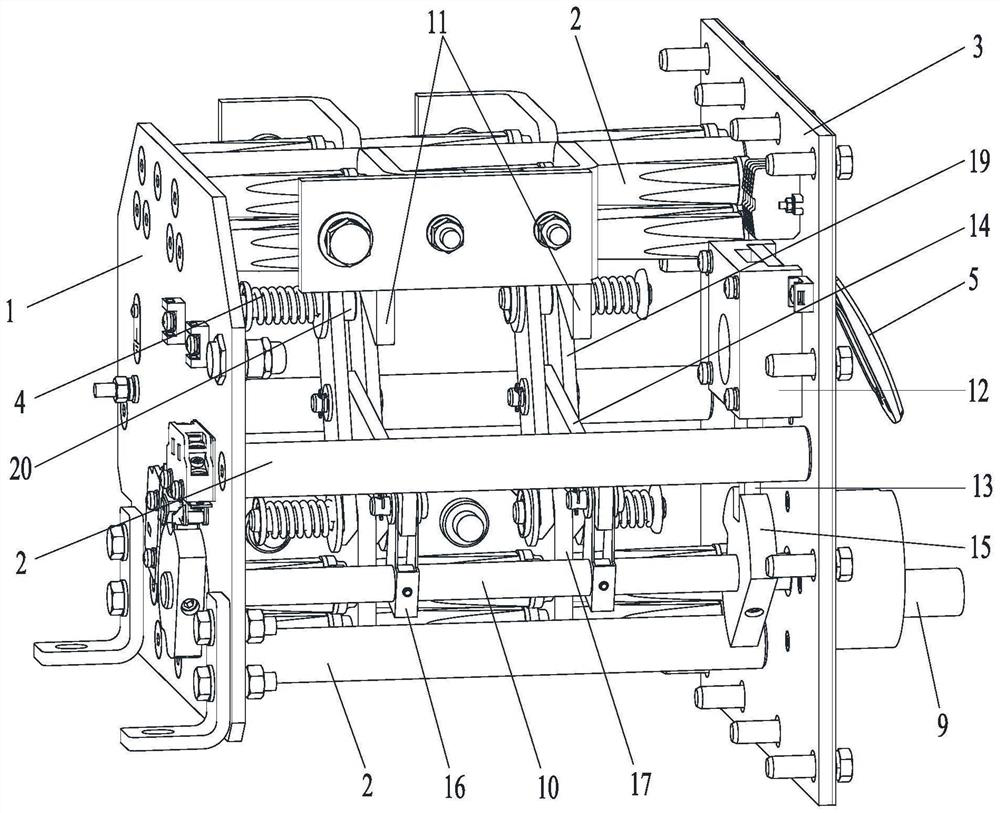
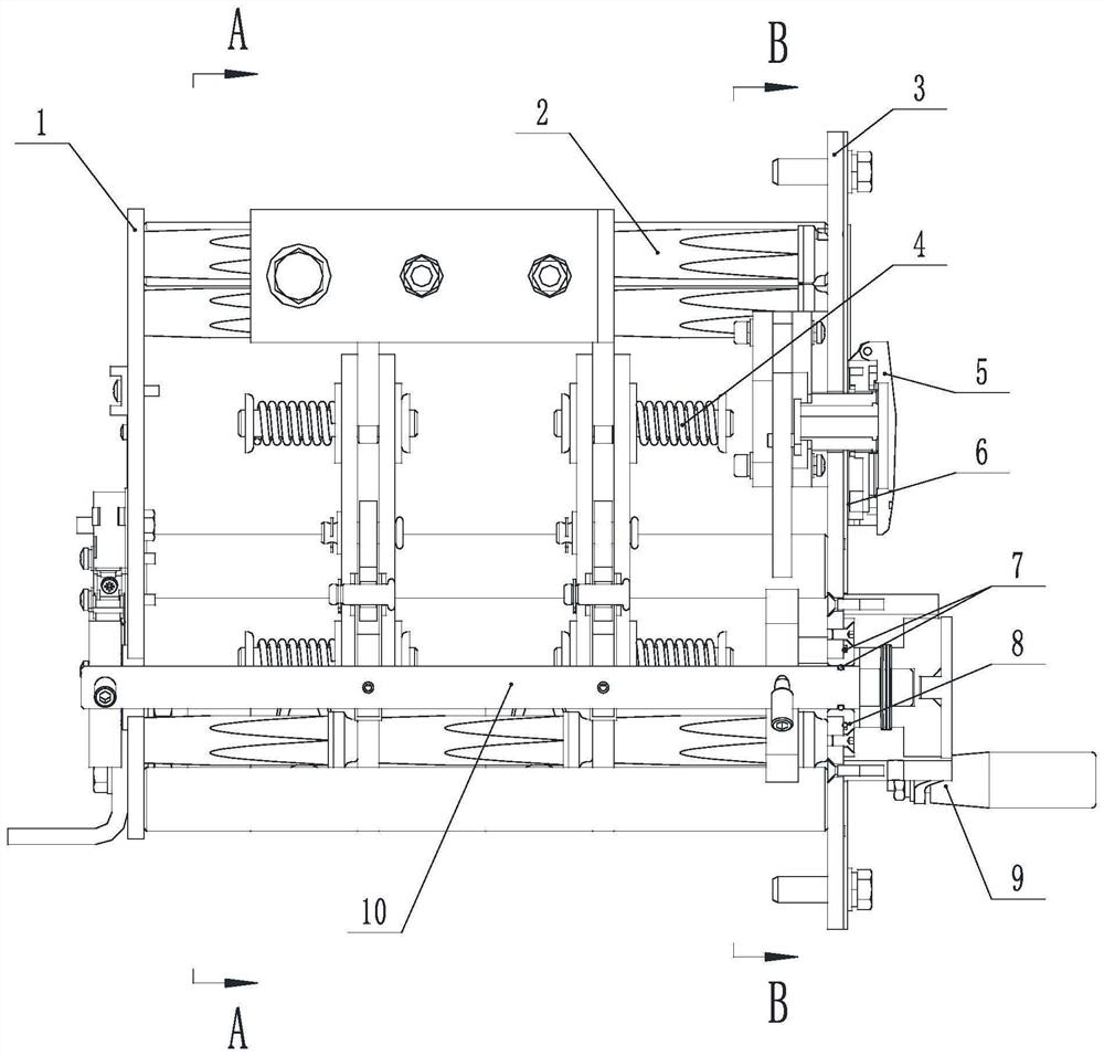
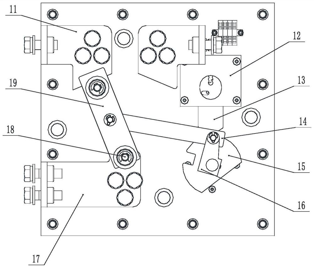
[0033] like Figures 1 to 4 As shown, the present invention provides a high-protection type self-compensating isolating switch with interlocking, comprising: a rear panel 1, an insulating column 2, a front panel 3, a compression sp...


PUM


Abstract

The invention discloses a high-protection type interlocking self-compensation disconnecting switch which comprises a front panel and a rear panel. A moving contact and two static contacts are arranged between the front panel and the rear panel, and the distance between the moving contact and the front panel or the distance between the static contacts and the rear panel are consistent. The moving contact is hinged with one end of the moving plate, the other end of the moving plate can be shifted between the two static contacts, hinged shafts or fixed shafts are arranged at two ends of the moving plate, compression springs are arranged on the hinged shafts or the fixed shafts, spacer bushes are arranged between the fixed shafts and the moving plate, and the thickness of the spacer bushes is smaller than that of the static contacts; the movable plate is in transmission with the main rotating shaft through a connecting assembly. The hinge shaft is hinged to the movable plate and the movable contact, the compression spring is arranged, rotation flexibility and compression reliability are guaranteed, the compression spring is arranged at the contact position of the movable plate and the static contact, the automatic compensation function of the contact position of the movable contact and the static contact is achieved, and therefore the movable contact and the static contact can be in good contact, and the service life of the movable contact and the static contact is prolonged. And the safety of the power supply circuit and power supply equipment is ensured.

Description

technical field [0001] The invention belongs to the technical field of power supply, and relates to an isolation switch, in particular to a high protection type self-compensating isolation switch with interlocking. Background technique [0002] The isolation switch is a high-voltage large-scale switch and an important device necessary for the power supply circuit. Its reliability directly determines the safety of the power supply circuit and power supply equipment. [0003] The isolation switch commonly used at present has the following defects: [0004] 1. When the moving contact and the static contact are closed, the contact area is guaranteed by the elasticity of the static contact itself. However, when the contact pressure is too large, the static contact is likely to cause rapid wear and tear. Since its own elasticity cannot compensate, so The contact area and contact pressure will be reduced accordingly; if the use time is long or the operating frequency is high, it w...

Claims


Application Information

Patent Timeline
Patent Type & Authority Applications(China)
IPC IPC(8): H01H31/02H01H9/04H01H3/02H01H31/04
CPCH01H31/02H01H9/04H01H3/02H01H31/04
Inventor 刘进刘恭智刘凡姜东宾高磊王奔王继斌程少龙
Owner XIANYANG YAHUA ELECTRONIC APPLIANCE CO LTD
Why Eureka
Try Eureka