
Method for determining optimal voltage vector of permanent magnet synchronous wind driven generator

A technology of wind power generator and voltage vector, which is applied in synchronous generator control, control of generator through magnetic field change, control of generator, etc. It can solve problems such as unfavorable system stable operation, stator current harmonic increase, magnetic saturation, etc. Achieve the effect of improving dynamic and static performance, small current pulsation and phase current harmonics, and reducing the number of predictions

Pending Publication Date: 2022-06-24
HUNAN UNIV OF TECH
View PDF0 Cites 0 Cited by
  • Summary
  • Abstract
  • Description
  • Claims
  • Application Information

AI Technical Summary

Problems solved by technology

The stator current pulsation and static difference caused by the voltage vector selection will not only cause the stator current harmonic increase and jitter, but also may cause magnetic saturation, which is not conducive to the stable operation of the system

Method used


Image

  • Method for determining optimal voltage vector of permanent magnet synchronous wind driven generator
  • Method for determining optimal voltage vector of permanent magnet synchronous wind driven generator
  • Method for determining optimal voltage vector of permanent magnet synchronous wind driven generator

Examples


Embodiment Construction

[0033] In order to describe the present invention more specifically, the present invention will be further described below with reference to the accompanying drawings and embodiments.

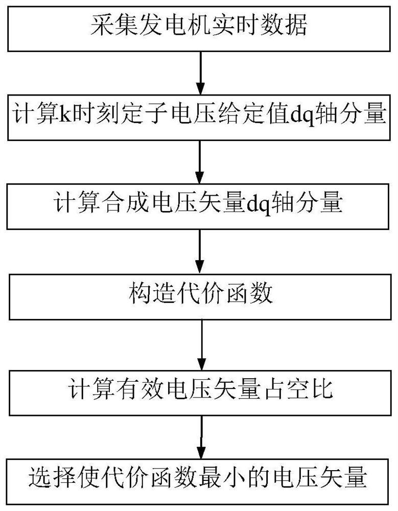
[0034] like figure 1 As shown, a method for determining an optimal voltage vector of a permanent magnet synchronous wind turbine, the steps include:

[0035] (1) Collect the real-time data of the generator, and calculate the dq-axis component of the given value of the stator voltage at time k

[0036] (2) Calculate the resultant voltage vector u s The dq-axis components of ;

[0037] (3) Constructing a cost function;

[0038] (4) Calculate the two adjacent effective voltage vectors u of the i-th sector mi , u ni The duty cycle d mi , d ni ;

[0039] (5) When d mi ni When < 0, the effect of the corresponding effective voltage vector is cancelled;

[0040] (6) When d mi >1 or d ni When >1, the corresponding effective voltage vector acts on the entire sampling period;

[0041] (7) W...


PUM


Abstract

The invention discloses a method for determining an optimal voltage vector of a permanent magnet synchronous wind driven generator, and the method specifically comprises the steps: collecting the real-time data of a generator, and calculating the dq-axis component of a stator voltage given value at a moment k; calculating a dq-axis component of the synthesized voltage vector us; constructing a cost function; calculating duty ratios dmi and dni of two adjacent effective voltage vectors umi and uni of the ith sector; when dmi is smaller than 0 or dni is smaller than 0, the function of the corresponding effective voltage vector is canceled, when dmi is larger than 1 or dni is larger than 1, the corresponding effective voltage vector acts on the whole sampling period, and when dmi is larger than or equal to 0 and smaller than or equal to 1 or dni is larger than or equal to 0 and smaller than or equal to 1, duty ratios dmi and dni are redistributed; and selecting two adjacent effective voltage vectors umi and uni which enable the cost function to be minimum. The stator current pulsation and static error of the permanent magnet synchronous wind driven generator can be effectively reduced, and the dynamic and static performance of the system is improved.

Description

technical field [0001] The invention belongs to the field of wind power conversion control, and in particular relates to a method for determining an optimal voltage vector of a permanent magnet synchronous wind generator. Background technique [0002] Direct-drive permanent magnet wind turbines have been widely used due to their advantages of eliminating the need for gearboxes, high power density and high efficiency. The stator current pulsation and static difference caused by the voltage vector selection will not only cause the stator current harmonic increase and jitter, but also may cause magnetic saturation, which is not conducive to the stable operation of the system. Therefore, it is necessary to design a method for determining the optimal voltage vector of permanent magnet synchronous wind turbines. SUMMARY OF THE INVENTION [0003] In view of the defects or deficiencies described in the background art, the present invention provides a method for determining the op...

Claims


Application Information

Patent Timeline
Patent Type & Authority Applications(China)
IPC IPC(8): H02P9/14H02P21/14H02P21/05H02P101/15H02P103/20
CPCH02P9/14H02P21/14H02P21/05H02P2101/15H02P2103/20Y02E10/76
Inventor 张阳张炎钦文定都
Owner HUNAN UNIV OF TECH
Learn More