Fundus imaging optical system
A technology of imaging optics and imaging light path, which is applied in ophthalmoscope, medical science, equipment for testing eyes, etc. It can solve problems such as affecting photography, unobtainable, weak light source, etc., to save device cost, improve accuracy and reliability Effect
- Summary
- Abstract
- Description
- Claims
- Application Information
AI Technical Summary
Problems solved by technology
Method used
Image

Examples
Embodiment 1
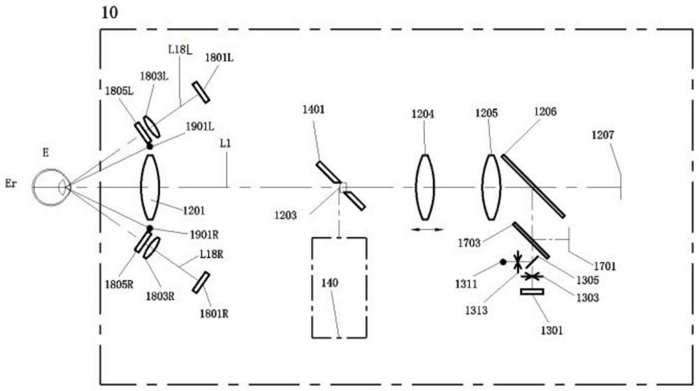
[0040] like figure 1 As shown in the figure, the lens shown in the figure is only a schematic diagram, and it can be formed in the form of a glued part or a mirror group, which belongs to common knowledge. The first probe 10 of the fundus imaging optical system includes: a fundus illumination light path, a fundus imaging light path, a fixation light path, and an auxiliary adjustment refractive light path; they are described as follows:
[0041] 1. Fundus illumination light path
[0042] The fundus illumination light path is used to provide fundus illumination with infrared light and white light flash to illuminate the fundus, so that the fundus imaging light path can realize infrared preview imaging of the fundus and flash photography imaging.
[0043] The fundus illumination light path includes the illumination light output light path 140 , the aperture mirror 1401 and the eyepiece objective lens 1201 . The light source (not shown) in the fundus illumination light path emit...
Embodiment 2
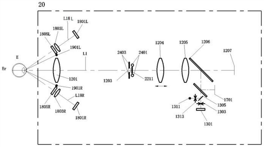
[0073] like image 3 As shown, the probe 20 also includes: a fundus illumination light path, a fundus imaging light path, a fixation light path, an auxiliary adjusting refractive light path, and an iris split image imaging light path. Only the parts different from those in Embodiment 1 will be described in detail below, and other parts will be referred to the descriptions in Embodiment 1.
[0074] 1. Fundus illumination light path
[0075] The fundus illumination light path includes an illumination light source 2401 , an illumination light filter 2403 and an eyepiece objective lens 1201 . The illumination light source 2401 emits light, which is transmitted through the light-emitting filter 2403 and the eyepiece objective lens 1201, and then passes through the human eye E to illuminate the fundus Er. Among them, the middle of the illuminating light filter 2403 has a second through hole, and the second through hole is provided with a second aperture 1203; the illumination ligh...
Embodiment 3
[0087] like Figure 4 As shown, the third probe 30 of the fundus imaging optical system also includes: a fundus illumination light path, a fundus imaging light path, a fixation light path, an auxiliary adjusting refractive light path, and an iris split imaging light path. Only the parts different from those in Embodiment 1 will be described in detail below, and other parts will be referred to the descriptions in Embodiment 1.
[0088] 1. Auxiliary adjustment of refractive path
[0089] The auxiliary adjustment and refraction path includes auxiliary adjustment and refraction light source 3301, pinhole aperture 3303, auxiliary adjustment and refraction path first lens 3304, double aperture aperture 3305, auxiliary auxiliary adjustment refraction path second lens 3306, fixed-refractive beam splitter 1703, The eye objective lens 1201 , the first diaphragm 1203 , the diopter lens 1204 , the imaging lens 1205 , the injection beam splitter 1206 , and the imaging device 1207 .
PUM
 Abstract
Description
Claims
Application Information
 - R&D Engineer
- R&D Manager
- IP Professional
- Industry Leading Data Capabilities
- Powerful AI technology
- Patent DNA Extraction
Browse by: Latest US Patents, China's latest patents, Technical Efficacy Thesaurus, Application Domain, Technology Topic.
© 2024 PatSnap. All rights reserved.Legal|Privacy policy|Modern Slavery Act Transparency Statement|Sitemap