Barrel-shaped nut mounting tool and using method thereof

A technology for installing tools and nuts, which is applied in the field of machinery, can solve problems such as abnormal or interference of the arched edge of the frame, difficulty in manual installation of barrel nuts, etc., and achieve the effects of avoiding deformation and interference, simple structure, and convenient operation

Active Publication Date: 2022-06-28
CHENGDU AIRCRAFT INDUSTRY GROUP
View PDF10 Cites 0 Cited by
  • Summary
  • Abstract
  • Description
  • Claims
  • Application Information

AI Technical Summary

Problems solved by technology

[0007] The invention aims to solve the problems of difficulty in manual installation of barrel nuts on site and abnormal or interference of the arched edge of the cage in the prior art, and proposes a barrel nut installation tool and its use method. The installation tool and method are easy to operate , simple, can quickly install the barrel nut in place

Method used


Image

  • Barrel-shaped nut mounting tool and using method thereof
  • Barrel-shaped nut mounting tool and using method thereof
  • Barrel-shaped nut mounting tool and using method thereof

Examples


Embodiment 1

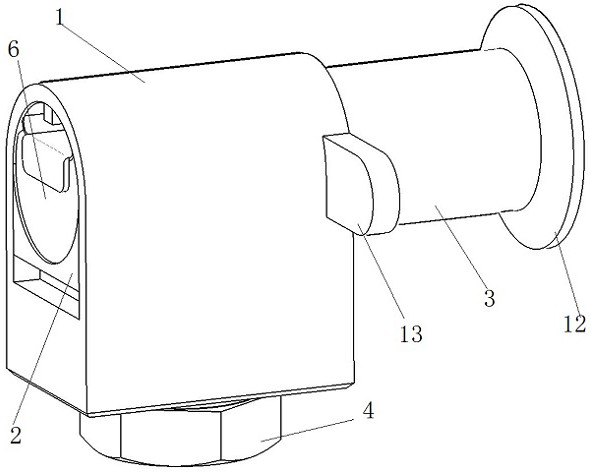
[0033] This embodiment provides a barrel nut installation tool, such as figure 1 As shown, it includes a sleeve 1 , a lower support 2 , a top rod 3 and a limiting member 4 .

[0034] Sleeve 1 is a hollow structure with openings at both ends, its upper half is a cylindrical structure with a partial arc surface inside, the lower half is a square base, and the upper half and the lower half are connected into a single structure. overall.

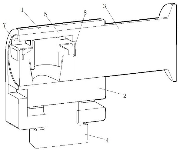
[0035] like figure 2 As shown in the figure, the lower support 2 is slidably connected inside the sleeve 1, and its bottom is slidably connected with the square base of the lower half of the sleeve 1 through a stepped structure. The part of the arc surface is opposite to the concave arc surface. The bottom of the square base is provided with threaded holes, and the limiting part 4 passes through the threaded holes at the bottom of the sleeve 1 and contacts with the lower support 2, and is used to adjust and fix the concave arc surface on the...

Embodiment 2

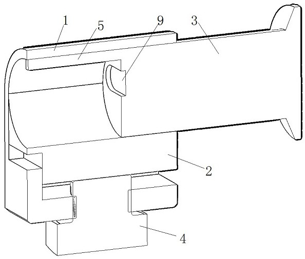
[0045]This embodiment provides a barrel nut installation tool. On the basis of Embodiment 1, further, the end of the ejector rod 3 in contact with the barrel nut assembly is provided with an escape groove 9, and the escape groove 9 just accommodates The elastic piece 8 protruding from the end face of the barrel nut assembly 6 side. In the process of pushing the ejector rod 3, the front end surface of the ejector rod 3 can be better contacted with the side end surface of the barrel nut assembly 6, so that it can bear the force better.

[0046] Preferably, in order to push the ejector rod 3 conveniently and labor-savingly, the end of the ejector rod 3 away from the barrel nut assembly is provided with a push handle 12 that is easy to hold, and the outer side of the sleeve 1 close to the ejector rod 3 is provided with a booster Connection ear 13.


PUM


Abstract

The invention discloses a barrel-shaped nut mounting tool and a using method thereof, and belongs to the technical field of machine.The barrel-shaped nut mounting tool comprises a sleeve, a lower support, an ejector rod and a limiting component, the sleeve is of a hollow structure with holes in the two ends, a partial cambered surface is arranged in the sleeve, and the lower support is slidably connected into the sleeve; the upper surface of the lower support is a concave arc surface opposite to a part of the arc surface on the sleeve, the limiting component penetrates through the sleeve and is in contact with the lower support, and the limiting component is used for adjusting and fixing a space defined by the concave arc surface of the lower support and the part of the arc surface of the sleeve; the barrel-shaped nut assembly and the ejector rod are installed in the space defined by the sleeve and the lower support in parallel, and the front end of the ejector rod is provided with a limiting needle used for preventing the barrel-shaped nut holder from being excessively compressed. The device is simple in structure and convenient to operate, and through structural design combination of the sleeve, the lower support, the ejector rod and the limiting component, installation of the barrel-shaped nut on a production site is greatly facilitated; and the difficulty of manually pressing the arched edge of the nut retainer is avoided.

Description

technical field [0001] The invention relates to the technical field of machinery, in particular to a barrel nut installation tool and a method of using the same. Background technique [0002] Chinese utility model patent CN2849294 discloses a barrel-shaped self-locking nut connector, the technical scheme of which is as follows: it includes a support, a self-locking nut and a retainer, and the support is a structure with a shape and size that is roughly the same as that of the hole to be connected. The half barrel-shaped body, the planes at both ends of the barrel extend radially to form a U-shaped through groove, a bolt through hole is formed in the groove, and a nut support seat and the through groove are assembled on the stepped surface of the U-shaped through groove. A self-locking nut with substantially the same diameter, shape and size is also clamped on the planes at both ends of the barrel body with an arc-curved elastic opening housing holder with a substantially rec...

Claims


Application Information

Patent Timeline
Patent Type & Authority Applications(China)
IPC IPC(8): B25B27/14
CPCB25B27/14
Inventor 李钧甫杨鹏涛蒋智华刘蕾庞林汪东明曾馨靓
Owner CHENGDU AIRCRAFT INDUSTRY GROUP
Why Eureka
Try Eureka