[0023] In order to illustrate the technical solutions in the embodiments of the present invention more clearly, the following briefly introduces the accompanying drawings used in the description of the embodiments. Obviously, the accompanying drawings in the following description are only preferred embodiments of the present invention. For those of ordinary skill in the art, other drawings can also be obtained from these drawings without creative effort.
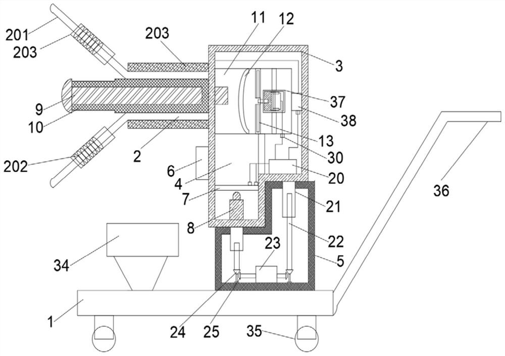
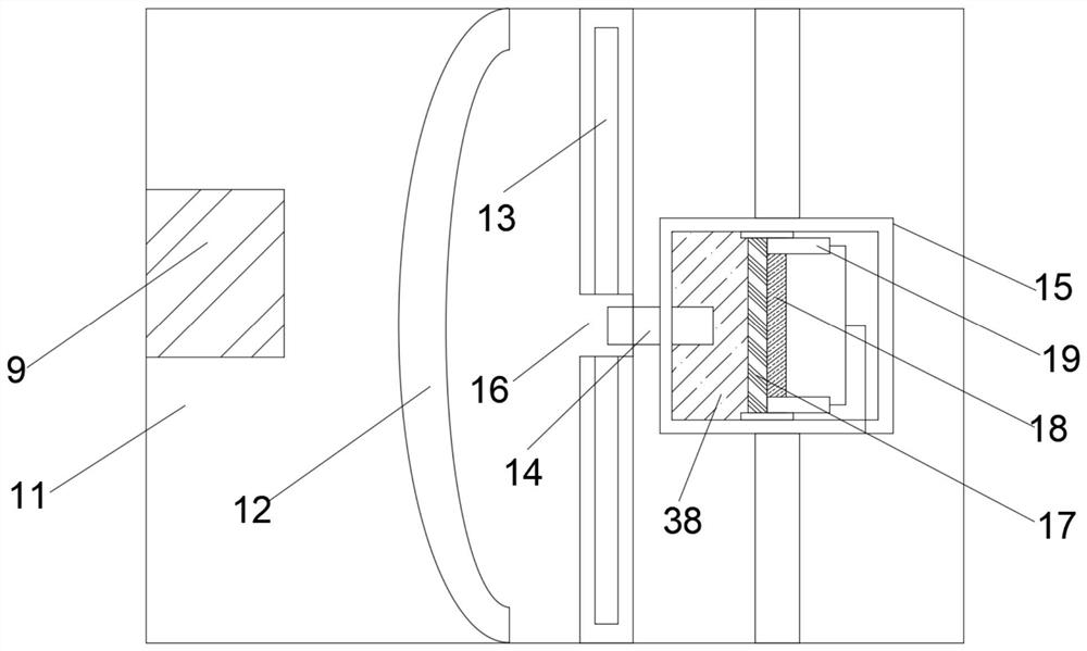
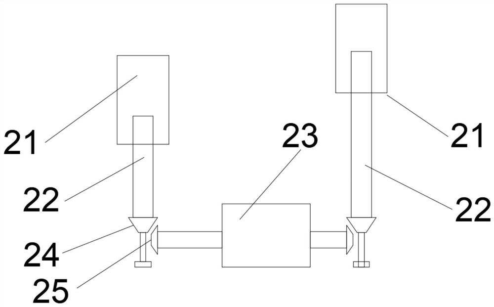
[0024] see Figure 1 to Figure 5 , an open circuit breaker partial discharge detection device based on the combination of sound and electricity, comprising a base 1, a driving device and a combined sound and electricity detection mechanism, the driving device is used to drive the sound and electricity combined detection mechanism to lift, so The sound and electricity combined detection mechanism includes a Y-shaped metal rod 2, a box body 3, an ultrasonic induction device, an electromagnetic induction box 37, an electrochromic glass 7, and a light source 8 arranged in the box body 3. A pulse receiving coil 202 is provided on each of the bifurcated support rods 201, a through hole is provided in the middle of the Y-shaped metal rod 2, and a first sound guide rod 9 is arranged in the through hole, and the first sound guide rod 9 is provided in the through hole. The end of the rod 9 is connected with the ultrasonic induction device, and the pulse receiving coil 202 is connected with the electromagnetic induction box 37 by the signal signal. The module 20 is electrically connected, the output end of the electric amplification module 20 is connected to the electrochromic glass 7, and a display cavity 4 is arranged in the box body 3, and the outer shell of the display cavity 4 is transparent glass, so The electrochromic glass 7 is fixed in the display cavity 4, the light source 8 is fixed directly below the electrochromic glass 7, and a smoke generator 6 is provided on one side of the display cavity 4, and the smoke generator 6 The outlet end is connected to the interior of the display cavity 4 .
[0025] The invention discloses an open circuit breaker partial discharge detection device based on the combination of sound and electricity, which can perform partial discharge detection on the open circuit breaker. During the detection, the base 1 is first transported to the open circuit breaker, and the acoustic and electricity are driven by the driving device. The joint detection mechanism is lifted to the highest point of the open circuit breaker. Since there are multiple protrusions on the outer surface of the open circuit breaker, the bifurcated support rod 201 in the Y-shaped metal rod 2 can just be clamped to the protrusion formed by the protrusion. In the groove, at the same time, the first sound guide rod 9 in the middle of the Y-shaped metal rod 2 can just stick to the outer surface of the open circuit breaker, and the ultrasonic wave generated by the circuit breaker during partial discharge is transmitted to the At the ultrasonic induction device, the ultrasonic induction device converts the received ultrasonic waves into current, and the circuit breaker will generate corresponding induced electricity at the pulse receiving coil 202 during partial discharge, and the induced electricity is amplified by the electromagnetic induction box 37;
[0026] The electric current obtained by the ultrasonic induction device and the electromagnetic induction box 37 is output to the electric amplification module 20 through the electric output terminal for secondary amplification, and the electric current after the secondary amplification is input into the electrochromic glass 7. When electricity is input, it is opaque, and when there is current input, it is transparent. When partial discharge occurs in the circuit breaker, the more serious the partial discharge is, the greater the current input to the electrochromic glass 7, the more transparent the electrochromic glass 7 is. Therefore, when the electrochromic glass 7 has current input, the light beam output from the light source 8 can pass through the electrochromic glass 7, and the smoke is input into the display cavity 4 through the smoke generator 6 arranged on one side of the display cavity 4. The light path of the light beam is displayed, and the user can observe whether there is a light beam and the brightness of the light beam through the transparent glass at the display cavity 4 with the naked eye, and judge whether the partial discharge and the occurrence of partial discharge occur by the presence or absence of the light beam and the brightness of the light beam. strength.
[0027] Specifically, the light source 8 is an infrared laser, and the smoke generator 6 is used to generate white smoke, and the combination of the white smoke and the red light beam is more convenient for the naked eye to identify and observe.
[0028]Specifically, the bifurcated support rod 201 is covered with a rubber insulating layer 203, and the pulse receiving coil 202 is arranged under the rubber insulating layer 203. The rubber insulating layer 203 avoids direct contact with the high-voltage part of the equipment to be detected, so as to ensure the overall dielectric strength.
[0029] Specifically, the outer surface of the first sound guide rod 9 is covered with a first metal shielding layer 10 , and the first metal shield layer 10 can eliminate the electrical signal on the support rod from causing the ultrasonic signal on the first sound guide rod 9 to cause interference.
[0030] Specifically, the box body 3 is provided with a first cavity 11 , and the ultrasonic induction device includes an acoustic lens 12 , a substrate 13 with small holes 16 , a second sound guide rod 14 and a sound guide cavity 15 . The first sound guide rod 9 extends into the first cavity 11 , the acoustic lens 12 is fixed in the first cavity 11 , and the center of the acoustic lens 12 is coaxial with the first sound guide rod 9 , The acoustic lens 12 , the substrate 13 , and the sound guide cavity 15 are arranged in sequence. One end of the second sound guide rod 14 extends to the small hole 16 , and the other end is fixed in the sound guide cavity 15 . 15 is provided with an elastic film 17 and a piezoelectric film 18 that are attached to each other, one side of the elastic film 17 has a sound guiding liquid 38, and the second sound guiding rod 14 is immersed in the sound guiding liquid 38, so Both ends of the piezoelectric film 18 are provided with film electrodes 19, and the film electrodes 19 are connected to the electrical output terminals through power lines.
[0031] The ultrasonic waves generated by the circuit breaker during partial discharge are transmitted to the acoustic lens 12 along the first sound guide rod 9. Under the converging action of the acoustic lens 12, the ultrasonic waves are concentrated at the small hole 16 in the middle of the middle substrate 13, and then along the first sound guide rod 9. The two sound guide rods 14 extend into the sound guide cavity 15 and are transmitted to the elastic film 17 along the sound guide liquid 38. Therefore, the elastic film 17 vibrates and drives the piezoelectric film 18 to vibrate, and the piezoelectric film 18 vibrates the mechanical energy generated by the vibration. It is converted into electrical energy, and is output to the electrical output terminal through the thin film electrode 19, and is output to the electrical amplifying module 20 from the electrical output terminal for current amplification.
[0032] Specifically, the electromagnetic induction box 37 is provided with a first-stage amplifying circuit 26 , a second-stage amplifying circuit 27 , a voltage regulator circuit 28 and a filter circuit 29 , the pulse receiving coil 202 and the first-stage amplifying circuit 26 , the second-stage amplifier circuit 27, the voltage regulator circuit 28, and the filter circuit 29 are electrically connected in sequence, and the output end of the filter circuit 29 is electrically connected to the electrical output end, and the induced electricity obtained by the pulse receiving coil 202 passes through the first The first-stage amplifying circuit 26 and the second-stage amplifying circuit 27 perform primary and secondary amplification, and the amplified current is regulated and filtered through the voltage stabilizing circuit 28 and the filter circuit 29, and is output to the electrical output terminal, where the electrical The output terminal is outputted to the electric amplifying module 20 for three-time current amplification.
[0033] Specifically, the electrical output end includes a terminal joint 30 , and the thin film electrode 19 and the filter circuit 29 are electrically connected to the corresponding terminal joint 30 through power lines, respectively.
[0034] Specifically, it also includes a display 34, a cloud platform 33, a main control microcontroller 32, and a current sensor 31. The terminal connector 30 is electrically connected to the electrical amplification module 20 through a wire, and the current sensor 31 is sleeved on the wire. Above, the current sensor 31 is signal-connected to the main control microcontroller 32 , the main control microcontroller 32 is connected to the cloud platform 33 through an intelligent gateway, and the display 34 is used to display the content of the cloud platform 33 .
[0035] The current on the wire can be detected by the current sensor 31, and the main control single-chip 32 generates a current waveform through the data of the current sensor 31, and transmits the above current data to the cloud platform 33 through the intelligent gateway, and the cloud platform 33 calculates the partial discharge point The display 34 is used to display the detection result transmitted by the cloud platform 33 .
[0036] Specifically, the box body 3 is in contact with the fixing part 5 , the driving device is arranged in the fixing part 5 , and the driving device includes two sliding cylinders 21 , a sliding rod 22 and a biaxial motor 23 . The sliding cylinders 21 are respectively fixed on both sides of the bottom of the box body 3 . One end of the sliding cylinder 21 is sleeved on the sliding rod 22 and is threadedly connected with the sliding rod 22 . The other end is provided with a driving bevel gear 24, the driving bevel gear 24 meshes with the driven bevel gear 25, the driven bevel gear 25 is fixed on the output end of the biaxial motor 23, and the biaxial motor 23 drives the driven bevel gear 25. The moving bevel gear 25 rotates, and the driven bevel gear 25 drives the driving bevel gear 24 to rotate, which in turn drives the sliding rod 22 to rotate. Under the action of the sliding cylinder 21 and the sliding rod 22, the sliding cylinder 21 moves upward and penetrates the the fixing part 5 , thereby pushing the box body 3 out of contact with the fixing part 5 .
[0037] Specifically, the base 1 is provided with a universal wheel 35, and one side of the base 1 is provided with a handle 36. Pushing the universal wheel 35 through the handrail facilitates the movement of the partial discharge detection device around the circuit breaker, thereby realizing the protection of the circuit breaker. Surround detection.
[0038] The above descriptions are only preferred embodiments of the present invention, and are not intended to limit the present invention. Any modifications, equivalent replacements, improvements, etc. made within the spirit and principles of the present invention shall be included in the present invention. within the scope of protection.