Control method and driving system of electric control three-way valve in fuel cell thermal management system

A thermal management system, fuel cell technology, applied in fuel cells, circuits, electrical components, etc., can solve problems such as inaccurate temperature control, and achieve the effect of ensuring control accuracy, saving manpower and time costs

Pending Publication Date: 2022-06-28
BEIJING SINOHYTEC
2 Cites 0 Cited by

AI-Extracted Technical Summary

Problems solved by technology

[0005] In view of the above analysis, the embodiment of the present invention aims to provide a control method for the electronically controlled three-way valve in the thermal m...

Abstract

The invention provides a control method and a driving system of an electric control three-way valve in a fuel cell thermal management system, belongs to the technical field of fuel cells, and solves the problem that the temperature control of the electric three-way valve is inaccurate along with the accumulation of switching times in the prior art. The method comprises the following steps: identifying the moment when the electric three-way valve is in a full-open or full-closed state, and starting timing; starting from the timing starting moment, collecting opening degree data of the electric three-way valve in a preset time period, and correcting the driving duty ratio of the electric three-way valve according to the opening degree data; the electric control three-way valve is controlled to execute the corrected driving duty ratio until the set learning time is reached, timing is ended, the actual maximum opening position and the actual minimum opening position of the electric three-way valve after the driving duty ratio is corrected are recognized, and then the set position of the electric three-way valve is corrected. The defect of feedback position deviation caused by switching frequency accumulation of the electric three-way valve is eliminated, and the thermal management control precision of the fuel cell is ensured.

Application Domain

Technology Topic

Thermal management systemMotronic +7

Image

  • Control method and driving system of electric control three-way valve in fuel cell thermal management system
  • Control method and driving system of electric control three-way valve in fuel cell thermal management system

Examples

  • Experimental program(3)

Example Embodiment

[0052] Example 1
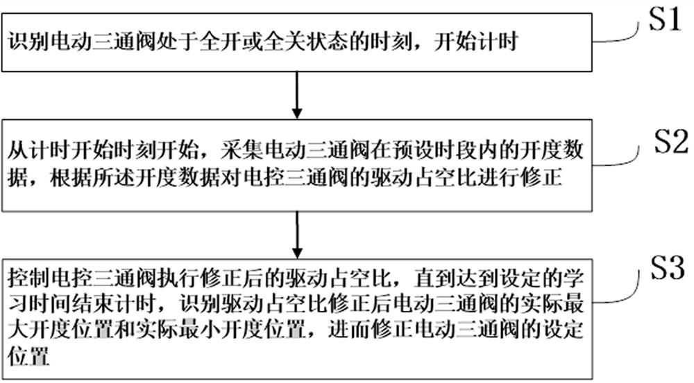
[0053] An embodiment of the present invention discloses a control method for an electronically controlled three-way valve in a fuel cell thermal management system, such as figure 1 shown, including the following steps:
[0054] S1. Identify the moment when the electric three-way valve is in the fully open or fully closed state, and start timing;
[0055] S2. From the timing start time, collect the opening degree data of the electric three-way valve within the preset time period, and correct the driving duty ratio of the electrically controlled three-way valve according to the opening degree data;
[0056] S3. Control the electronically controlled three-way valve to execute the corrected drive duty cycle until the set learning time is reached, and identify the actual maximum opening position and actual minimum opening position of the electric three-way valve after the drive duty cycle is corrected. , and then correct the set position of the electric three-way valve (set the maximum opening position, set the minimum opening position).
[0057] For the fuel cell thermal management system, please refer to patent CN202110344729.0 or CN202110246819.6.
[0058] Compared with the prior art, this embodiment provides a self-learning correction method for an electronically controlled three-way valve in a fuel cell thermal management system, so that the electric three-way valve performs self-learning correction at a specific time, which can effectively eliminate the switching times. Influence of deviation of drive cycle and set position caused by accumulation.

Example Embodiment

[0059] Example 2
[0060] On the basis of embodiment 1, improve, also include the following steps:
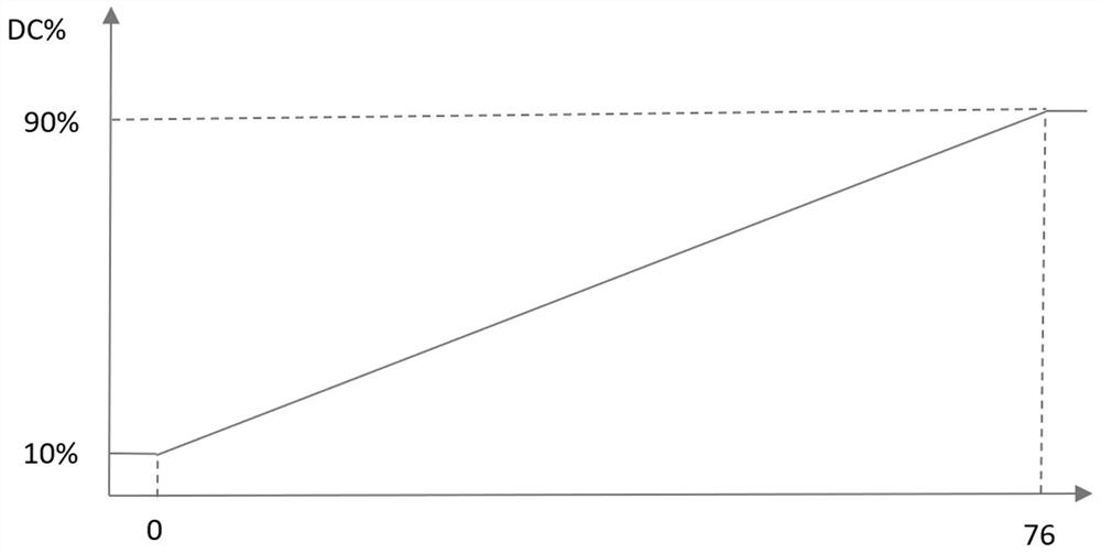
[0061] S01. Determine the characteristic curve of the opening degree of the electric three-way valve changing with the number of switches, such as figure 2 shown;
[0062] S02. According to the above characteristic curve, determine the time period during which the electric three-way valve enters the self-learning correction, as well as the initial learning time t0, learning time t1, maximum opening B1, and minimum opening B2 in each time period; Each time the opening degree change rate of the three-way valve decreases by a fixed ratio, a self-learning correction is performed, and the learning time t1 is greater than an integer multiple of the drive period set by the factory. The maximum opening B1 and the minimum opening B2 are also the initial installed values ​​provided by the electric three-way valve manufacturer.
[0063] Preferably, during each self-learning correction, the preset time period is set such that the end time of the preset time period is greater than or equal to the start time t0, and includes at least one factory-set drive cycle.
[0064] Preferably, in step S1, the step of identifying the moment when the electric three-way valve is in a fully open or fully closed state further includes:
[0065] S11. Obtain the target opening A and the actual opening A1 of the electric three-way valve at the current moment;
[0066] S12. Determine whether the electric three-way valve is in a fully open or fully closed state according to the target opening A and the actual opening A1; if A=100% (the target opening is fully open) and A1=100% (the actual opening fully open) or A=0 and A1=0, determine the moment when the electric three-way valve is in the fully open or fully closed state, otherwise, obtain the target opening and actual opening of the electric three-way valve at the next moment again, until Identify the moment when the electric three-way valve is fully open or fully closed.
[0067] Preferably, step S2 further comprises:
[0068] S21. From the timing start time to the end time of the preset period, obtain the actual opening data, duration and the electric three-way valve when the target opening is 100% (full opening) and 0, respectively. The target opening data and duration when the actual opening is the maximum and 0;
[0069] S22. According to the above-mentioned actual opening degree data, target opening degree data and respective durations, obtain the corrected driving duty ratio Pwm1 of the electric three-way valve. Pwm1>0. Optionally, the corrected driving duty cycle can be obtained through data fitting or modeling statistics, which can be understood by those skilled in the art.
[0070] Preferably, step S22 can also further adopt the following method:
[0071] S221. Input the above-mentioned actual opening data, target opening data and their respective durations into the pre-trained neural network respectively to obtain the corrected driving duty ratio of the electric three-way valve.
[0072] Training data can be obtained through data fitting or modeling. The revised driving direction is consistent with the driving discovery of the electric three-way valve at the current moment, and does not change.
[0073] The correction of the set position in step S3 can be re-timed, or the above-mentioned time can be continued. It is only necessary to ensure that the signal acquisition time in steps S31 and S32 reaches the set learning time t1.
[0074] Preferably, in step S3, the step of identifying the actual maximum opening position and the actual minimum opening position of the electric three-way valve after the driving duty ratio is corrected, and then correcting the set position of the electric three-way valve further comprises:
[0075] S31. Obtain the actual opening position of the electric three-way valve when the target opening of the electric three-way valve is 100% after the drive duty ratio is corrected, as the corrected set maximum opening position of the electric three-way valve;
[0076] S32. Obtain the actual opening position of the electric three-way valve when the driving duty ratio is 0, and the actual opening position of the electric three-way valve when the target opening of the electric three-way valve is 0 after the driving duty ratio is corrected. It is the minimum opening position after the correction of the electric three-way valve.
[0077] Or, S31. Obtain the actual opening position when the target opening of the electric three-way valve is 100% after the driving duty ratio correction and the target opening position when the actual opening is the largest, and take the average value of the two as the electric three-way valve The revised set maximum opening position;
[0078] S32. Obtain the actual opening position of the electric three-way valve when the driving duty ratio is 0, and the actual opening position when the target opening of the electric three-way valve is 0 after the driving duty ratio is corrected, and the actual opening position when the actual opening is the largest The target opening position, the average value of the three is used as the corrected minimum opening position of the electric three-way valve.
[0079] Then, the corrected drive duty ratio and the corrected set position of the electric three-way valve obtained above are saved
[0080] It should be noted that the opening position refers to the coordinate position of the three-way valve switch, and the opening is 0~100%.
[0081] Compared with the prior art, the method of this embodiment has the following beneficial effects:
[0082] 1. The driving duty ratio and setting position of the electric three-way valve can be automatically corrected to ensure the thermal management control accuracy of the fuel cell and save manpower and time costs.
[0083] 2. A self-learning algorithm for electric three-way valve is developed, which enables the electric three-way valve to perform self-learning correction of the position characteristic curve at a specific time, and solves the problem of deviation of the feedback position caused by the accumulation of switching times of the electric three-way valve.

Example Embodiment

[0084] Example 3
[0085] The present invention also discloses a driving system for an electronically controlled three-way valve in a fuel cell thermal management system corresponding to the method in Embodiment 1 or 2, comprising a controller and an electronically controlled three-way valve connected in sequence.
[0086] The controller is used to control the start of the electronically controlled three-way valve; and, after the electronically controlled three-way valve is started, identify whether to enter the self-learning correction stage; if so, identify the moment when the electric three-way valve is in a fully open or fully closed state, Start timing, collect the opening data of the electric three-way valve within the preset time period from the time when the timing starts, and correct the driving duty ratio of the electronically controlled three-way valve according to the opening data, and then control the electronically controlled three-way valve. The through valve executes the corrected drive duty cycle until the set learning time is over, and the actual maximum opening position and the actual minimum opening position of the electric three-way valve after the drive duty cycle correction is identified, and then the electric three-way valve is corrected. The set position of the valve.
[0087] Preferably, the controller further comprises a position sensing module, a data processing and control module, and a driving module which are connected in sequence.
[0088] Drive module, built-in drive duty cycle and set position, used to drive the electronically controlled three-way valve to start.
[0089] The position sensing module is used to collect the actual opening data of the three-way valve and send it to the data processing and control module.
[0090] The data processing and control module is used to identify whether to enter the self-learning correction stage after the electronically controlled three-way valve is activated; if so, identify the moment when the electric three-way valve is in a fully open or fully closed state, and start timing from the time the timing starts. Start by collecting the opening data of the electric three-way valve within a preset period of time, correcting the driving duty ratio of the electronically controlled three-way valve according to the opening data, and sending the corrected driving duty ratio to the drive module Replace its built-in drive duty cycle until the set learning time ends, identify the actual maximum opening position and the actual minimum opening position of the electric three-way valve after the drive duty cycle is corrected, and then correct the electric three-way valve. Set the position and send the corrected set position to the drive module to replace its built-in set position.
[0091] Preferably, the data processing and control module executes the following procedures:
[0092] SS1. Determine the characteristic curve of the opening degree of the electric three-way valve changing with the number of switches;
[0093] SS2. According to the above characteristic curve, determine the time period during which the electric three-way valve enters the self-learning correction, as well as the initial learning time t0, learning time t1, maximum opening B1, and minimum opening B2 in each time period; Each time the opening degree change rate of the three-way valve decreases by a fixed ratio, a self-learning correction is performed, and the learning time t1 is greater than an integer multiple of the drive period set by the factory;
[0094] SS3. After the electronically controlled three-way valve is started, identify whether to enter the self-learning correction stage; if so, execute the next step; otherwise, control the electronically controlled three-way valve to drive according to the built-in drive duty cycle and set position of the drive module;
[0095] SS4. Identify the moment when the electric three-way valve is fully open or fully closed, and start timing;
[0096] SS5. From the timing start time, collect the opening data of the electric three-way valve within the preset period, correct the driving duty ratio of the electronically controlled three-way valve according to the opening data, and use the corrected driving The duty cycle is sent to the drive module to replace its built-in drive duty cycle;
[0097] SS6 controls the electronically controlled three-way valve to execute the corrected drive duty cycle until the set learning time ends, and identifies the actual maximum opening position and the actual minimum opening position of the electric three-way valve after the drive duty cycle is corrected. Then correct the set position of the electric three-way valve, and send the corrected set position to the drive module to replace its built-in set position;
[0098] SS7. Control the electronically controlled three-way valve to perform the corrected set position.

PUM

no PUM

Description & Claims & Application Information

We can also present the details of the Description, Claims and Application information to help users get a comprehensive understanding of the technical details of the patent, such as background art, summary of invention, brief description of drawings, description of embodiments, and other original content. On the other hand, users can also determine the specific scope of protection of the technology through the list of claims; as well as understand the changes in the life cycle of the technology with the presentation of the patent timeline. Login to view more.

Similar technology patents

Turntable control system and control method thereof

Owner:OPTIMUS ROBOT AUTOMATION SUZHOU CO LTD

A torque control method, device, terminal equipment and storage medium

ActiveCN112987812BImprove dynamic response performanceGuaranteed control accuracyMechanical power/torque controlElectric energy managementElectric machineryProportional derivative
Owner:UBTECH ROBOTICS CORP LTD

High-speed magnetic levitation motor with novel air cooling structure

Owner:天津飞旋高速电机科技有限公司 +1

EGR rate control method and device

ActiveCN113685280AGuaranteed Control AccuracyRealize dynamic controlElectrical controlExhaust gas recirculationFresh airLoop control
Owner:GUANGZHOU AUTOMOBILE GROUP CO LTD

Classification and recommendation of technical efficacy words

  • Guaranteed control accuracy
  • Save manpower and time cost

High-flow high-frequency-response digital valve capable of rotating and being controlled in parallel

ActiveCN103541943AGuaranteed control accuracyHigh frequency responseServomotor componentsEngineeringMotor drive
Owner:NANTONG METALFORMING EQUIP

Automatic continuous testing device and method for coal and rock permeability under non-equilibrium state

ActiveCN110068527AGuaranteed control accuracySimple connecting pipe structurePermeability/surface area analysisPressure controllerEquilibrium constant
Owner:CHINA UNIV OF MINING & TECH

Steering control method and steering control device

ActiveCN108860293AImprove transmission precision and steering precisionGuaranteed control accuracyElectrical steeringSteering angleSteering control
Owner:BEIJING ZHIXINGZHE TECH CO LTD
Why Eureka
Try Eureka