
Separable solid waste treatment equipment

A technology for processing equipment and solid waste, applied in the direction of grain processing, etc., can solve the problems of inability to clean the crushing cavity, poor crushing treatment quality, and poor separation quality, so as to improve the cleaning effect and cleanliness, and reduce the process of secondary separation, The effect of improving the separation effect

Pending Publication Date: 2022-07-01
山东高洁环保科技有限公司
View PDF0 Cites 0 Cited by
  • Summary
  • Abstract
  • Description
  • Claims
  • Application Information

AI Technical Summary

Problems solved by technology

[0004] 1. When the processing equipment is in use, the crushed waste cannot be transported to the slant plate in batches. Too much crushed waste is piled up together, so that it is easy to cause poor separation quality when it is discharged into the collection frame, which in turn increases the burden on the waste. The process of crushing waste for secondary separation reduces the separation effect of treatment equipment;
[0005] 2. After the processing equipment is used, the crushing cavity cannot be fully cleaned. If the cleaning of the crushing cavity is not thorough, there will still be dirt on the inner wall, which will easily lead to inconvenience for the next processing. At the same time, the crushing structure cannot be cleaned, and the surface of the crushing structure Impurities left on the wall cause corrosion, which can easily lead to poor crushing quality and reduce the cleaning effect and cleanliness of the processing equipment

Method used


Image

  • Separable solid waste treatment equipment
  • Separable solid waste treatment equipment
  • Separable solid waste treatment equipment

Examples


Embodiment Construction

[0022] The technical solutions in the embodiments of the present invention will be clearly and completely described below with reference to the accompanying drawings in the embodiments of the present invention. Obviously, the described embodiments are only a part of the embodiments of the present invention, but not all of the embodiments. Based on the embodiments of the present invention, all other embodiments obtained by those of ordinary skill in the art without creative efforts shall fall within the protection scope of the present invention.

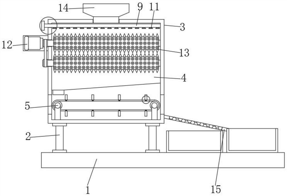
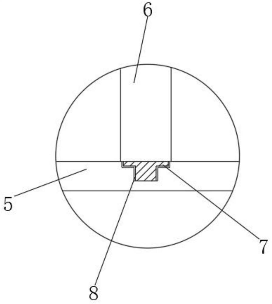
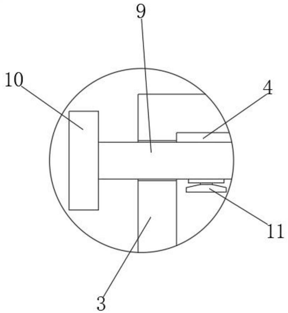
[0023] see Figure 1-4 , in this embodiment: a separable solid waste treatment equipment, comprising a base plate 1, the upper end of the base plate 1 is provided with a support leg 2, the upper end of the support leg 2 is provided with a treatment box 3, and the interior of the treatment box 3 is provided with a pulverizing cavity 4. The lower end of the crushing chamber 4 is provided with a conveying structure 5, the outer wall of t...


PUM


Abstract

The invention discloses separable solid waste treatment equipment which comprises a bottom plate, supporting legs are arranged at the upper end of the bottom plate, a treatment box is arranged at the upper ends of the supporting legs, a crushing cavity is formed in the treatment box, a conveying structure is arranged at the lower end of the crushing cavity, a partition plate is arranged on the outer surface wall of the conveying structure, and a mounting block is arranged at one end of the partition plate. A mounting groove is formed outside the mounting block and located in the conveying structure, a cleaning pipe is arranged in the crushing cavity, a water inlet is formed in one end of the cleaning pipe, and a water spraying opening is formed in the outer surface wall of the cleaning pipe. According to the separable solid waste treatment equipment, by arranging the partition plate, the mounting block and the mounting groove, crushed waste can be conveyed to a discharging inclined plate in batches, and the problem that too much crushed waste is stacked together, so that the crushed waste is discharged into a collecting frame, and the separation quality is poor is solved; and therefore, the procedure of secondary separation of the crushed waste is reduced.

Description

technical field [0001] The invention relates to the technical field of treatment equipment, in particular to a separable solid waste treatment equipment. Background technique [0002] With the development of society and the increase of population, more and more domestic wastes are produced by human beings, which leads to increasingly serious environmental protection problems, which makes the problem of garbage become one of the serious problems that human beings need to face. Usually, people dispose of garbage. One of the main methods is landfill treatment, that is to find a place, dig a deep pit, and bury the garbage in it, but when the existing solid waste is landfilled, when the volume of the solid waste is large, it will cause waste. The decomposition rate is slow. Therefore, people usually pulverize the solid waste before landfilling the solid waste, and then use the treatment equipment to pulverize the solid waste. The proposed treatment equipment can The waste is sep...

Claims


Application Information

Patent Timeline
Patent Type & Authority Applications(China)
IPC IPC(8): B02C4/08B02C4/28B02C23/20B02C23/16
CPCB02C4/08B02C4/28B02C23/20B02C23/16B02C2023/165B02C2201/06
Inventor 不公告发明人
Owner 山东高洁环保科技有限公司
Learn More