Reduction gearbox

A reduction box and planetary reduction technology, applied in mechanical control devices, transmission devices, instruments, etc., can solve the problems of limited use range and inconvenient use, and achieve the effect of convenient use and widening of the application range.

Pending Publication Date: 2022-07-01
HUBEI KEFENG TRANSMISSION EQUIP CO LTD
View PDF0 Cites 0 Cited by
  • Summary
  • Abstract
  • Description
  • Claims
  • Application Information

AI Technical Summary

Problems solved by technology

During the use of the existing reducer, once it is connected to the motor, it can only be in the working state of deceleration, and it cannot be in the working state of not decelerating but only transmitting torque, which limits its scope of use and makes it not convenient to use

Method used


Image

  • Reduction gearbox
  • Reduction gearbox
  • Reduction gearbox

Examples


Embodiment Construction

[0032] The preferred embodiments of the present invention are specifically described below with reference to the accompanying drawings, wherein the accompanying drawings constitute a part of the present application, and together with the embodiments of the present invention, are used to explain the principles of the present invention, but are not used to limit the scope of the present invention.

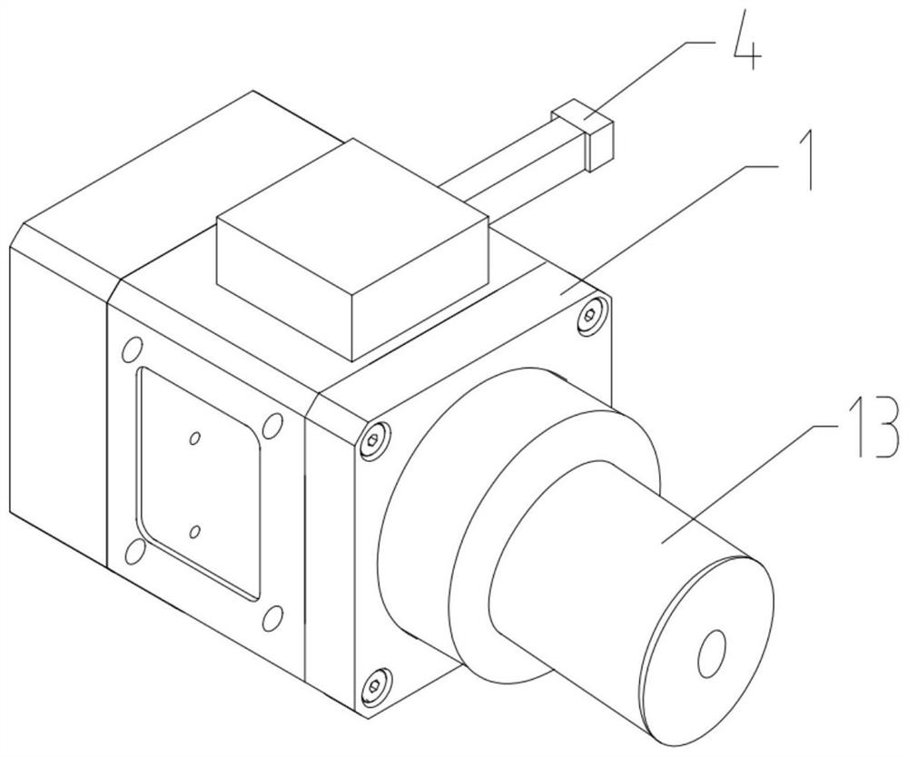
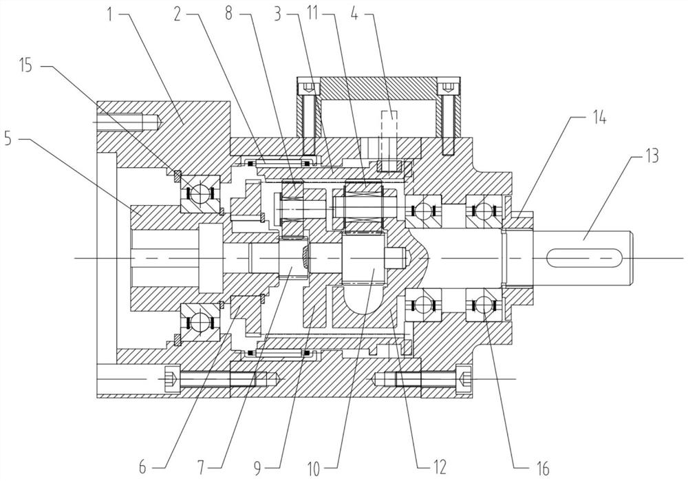
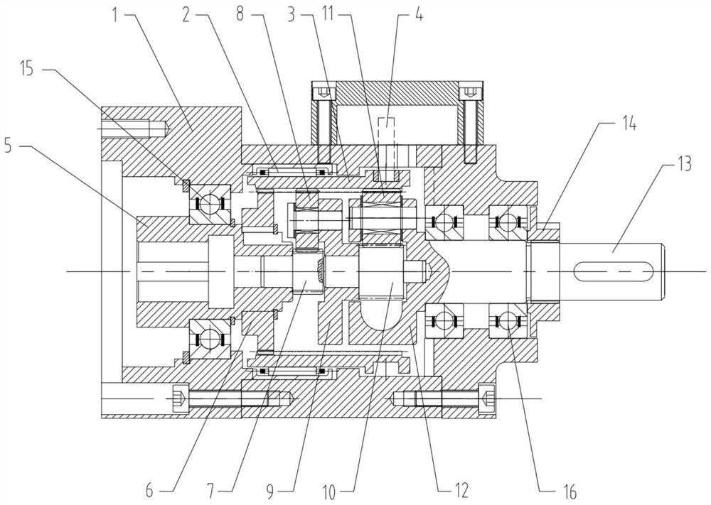
[0033] Please refer to Figure 1 to Figure 4 , an embodiment of the present invention provides a reduction box, including: a casing 1, a coupling 5, a speed-adjusting ring gear 3, a planetary reduction mechanism, a fork switch 4 and an output shaft 13;

[0034] The coupling 5 is rotatably arranged at one end of the housing 1 through the first bearing 15; one end of the coupling 5 is provided with a synchronizing gear 6 for meshing with the speed regulating ring gear 3; the other end of the coupling 5 For connecting with external power source;

[0035] The speed regulating ring gear ...


PUM


Abstract

The invention provides a reduction gearbox, and relates to the field of speed reducers. The reduction gearbox comprises a shell, a coupler, a speed regulation gear ring, a planetary reduction mechanism, a shifting fork switch and an output shaft. The coupling is rotatably arranged at one end in the shell; a synchronous gear is arranged at one end of the coupler and used for being meshed with the speed regulation gear ring. The speed regulating gear ring is arranged in the shell; the planetary speed reducing mechanism is rotatably arranged in the speed regulating gear ring and is meshed with the speed regulating gear ring; the output shaft is fixedly arranged on the planetary reducing mechanism and extends to the outside from the other end of the shell; the shifting fork switch is arranged on the shell and is used for adjusting the circumferential motion state of the speed regulation gear ring, so that the speed regulation gear ring can be in a fixed state or a rotatable state; when the speed regulating gear ring is in a rotatable state, the speed regulating gear ring is meshed with the synchronous gear; the working state of the reduction gearbox can be adjusted according to use requirements, so that the reduction gearbox can be in the working state of speed reduction and can also be in the working state that only torque is transmitted without speed reduction.

Description

technical field [0001] The invention relates to the field of speed reducers, in particular to a speed reducer capable of adjusting the working state. Background technique [0002] The reducer is a power transmission mechanism that uses the speed converter of the gear to reduce the number of revolutions of the motor to the required number of revolutions and obtain a large torque. Among the mechanisms currently used to transmit power and motion, the reducer has a wide range of applications, and its traces can be seen in almost all kinds of mechanical transmission systems. The reducer is a relatively precise machine. The purpose is to reduce the speed and increase the torque. In the process of using the existing reducer, once connected to the motor, it can only be in the working state of deceleration, and cannot make it in the working state of not decelerating but only transmitting torque, which limits its scope of use, resulting in inconvenient use. SUMMARY OF THE INVENTION...

Claims


Application Information

Patent Timeline
IPC IPC(8): F16H3/46F16H57/021F16H57/023F16H57/08F16H63/32
CPCF16H3/46F16H57/021F16H57/023F16H57/08F16H63/32F16H2063/321F16H2063/322
Inventor 何文静
Owner HUBEI KEFENG TRANSMISSION EQUIP CO LTD
Why Eureka
Try Eureka