
Production process of large-diameter flexible composite pipe

A flexible composite pipe and production process technology, applied in the direction of coating, etc., can solve the problems of difficult-to-form inner lining pipe layer, low strength, easy bending or breaking of pipe blanks, etc., and achieve the effect of widening the scope of application and high strength

Pending Publication Date: 2021-12-28
宝鸡天联汇通复合材料有限公司
View PDF16 Cites 0 Cited by
  • Summary
  • Abstract
  • Description
  • Claims
  • Application Information

AI Technical Summary

Problems solved by technology

[0003] Since composite pipes are generally made of non-metallic materials by melting raw materials, they have lower strength than metal pipes. Especially in the process of melting preparation, the raw materials need to be melted and then extruded into composite closures. In this process Among them, due to the high temperature of the raw material when it is melted, it also has a high temperature of the pipe body after being extruded into a tube blank. Under the action of gravity, the tube billet at a certain temperature is prone to bending or breaking. Therefore, the manufacture of large-diameter composite pipes has always been a major difficulty in the field of composite pipes, which in turn affects the transportation of large-capacity oil, natural gas or other media. Obstacles
[0004] Composite pipes are generally composed of multi-layer pipes of different materials, including inner lining layers, intermediate reinforcement layers and outer cladding layers, etc. The production process is as follows: firstly, the inner lining pipe layer is made, and the inner lining pipe layer is formed. On the basis of forming the layer and having a certain strength, the inner liner layer is then coated with an intermediate reinforcement layer and an outer cladding layer in sequence. Therefore, the main difficulty for large-diameter composite pipes is that it is difficult to form the inner liner layer.

Method used


Image

  • Production process of large-diameter flexible composite pipe
  • Production process of large-diameter flexible composite pipe
  • Production process of large-diameter flexible composite pipe

Examples


Embodiment Construction

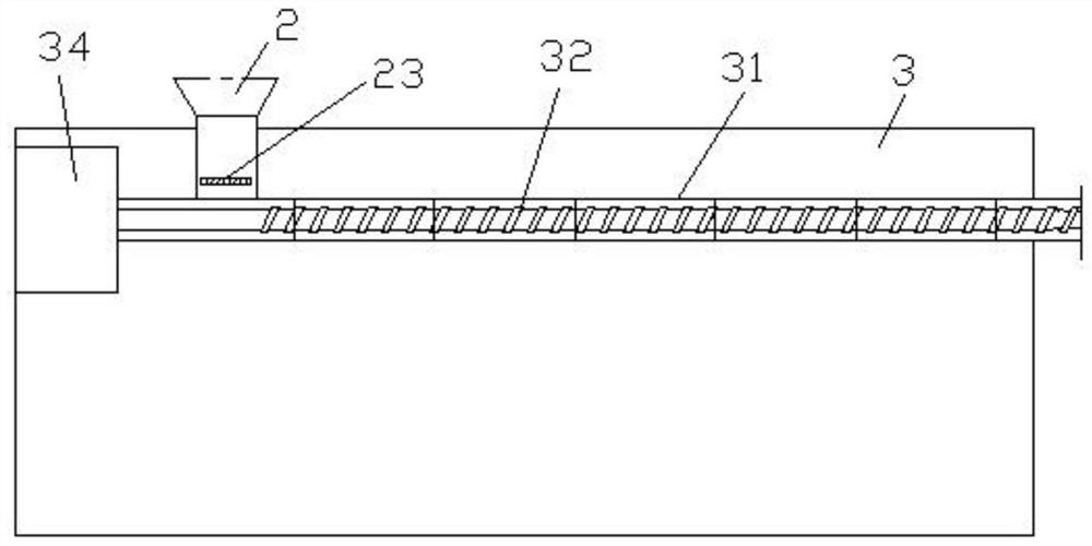
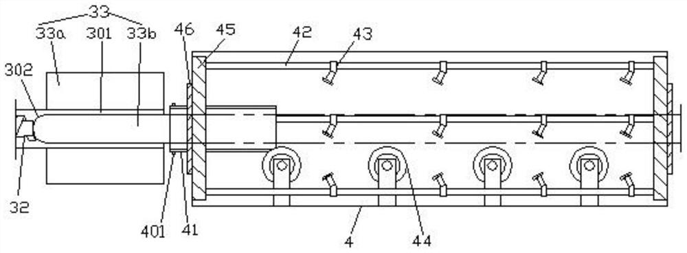
[0029] In order to enable those skilled in the art to better understand the technical solution of the present invention, the technical solution of the present invention will be further described below in conjunction with the accompanying drawings and embodiments.

[0030] Refer to attached Figure 1-10 The production process of a large-diameter flexible composite pipe shown includes the following equipment in sequence: a suction machine 1, which is used to absorb and transport the pipe-making raw material (preferably granular polyethylene) to the storage cylinder at a rated capacity and speed 2; material storage tank 2 (with feed port 21 and material discharge port 22), the raw material transported by the suction machine 1 is entered from the feed port 21 for storage, and at the same time the rated capacity and speed (at the bottom of the storage tank 2) The plug-in regulating plate 23) is transported to the screw extruder 3 through the discharge port 22; the screw extruder 3 ...


PUM


Abstract

The invention discloses a production process of a large-diameter flexible composite pipe. The production process sequentially comprises the following equipment: a material suction machine, a material storage barrel, a screw extruder, a vacuum shaping box, a spray cooling box, a traction machine and outer coating layer coating equipment. According to the production process, the difficulty in forming a lining pipe layer of the large-diameter composite pipe can be effectively overcome, so that the lining pipe layer prepared by the production process has the advantages of large diameter and high strength, and particularly, in the preparation process, due to the control requirement on the strength of the lining pipe layer, the lining pipe layer of the large-diameter composite pipe is formed on the premise of overcoming the manufacturing difficulty, the blank of production of the lining pipe layer of the large-diameter composite pipe is filled, and the application range of the composite pipe is widened.

Description

technical field [0001] The invention relates to Liang Yu, a large-diameter composite pipe manufacturing technology, in particular to a production process of a large-diameter flexible composite pipe. Background technique [0002] Composite pipe is a kind of oil and gas industry pipe fittings made of polymer composite materials with high strength, high pressure, corrosion resistance, scaling resistance, small friction coefficient, good heat preservation, good flexibility and long service life. . According to the application, it is divided into composite pipes for oil transportation, composite pipes for gas transportation, composite pipes for water transportation, composite pipes for alcohol injection, etc. [0003] Since composite pipes are generally made of non-metallic materials by melting raw materials, they have lower strength than metal pipes. Especially in the process of melting preparation, the raw materials need to be melted and then extruded into composite closures. ...

Claims


Application Information

Patent Timeline
IPC IPC(8): B29C48/09B29C48/25B29C48/355B29C48/395B29C48/88B29C48/90B29C37/00B29C48/00B21F3/04B29K23/00
CPCB29C48/09B29C48/25B29C48/355B29C48/397B29C48/9115B29C48/901B29C37/0092B29C48/001B21F3/04B29K2023/06
Inventor 贾康康
Owner 宝鸡天联汇通复合材料有限公司
Learn More