Wind cap dredging and slag collecting equipment for power station boiler

A technology for power station boilers and collection equipment, applied in lighting and heating equipment, removal of solid residues, combustion methods, etc., can solve the problems of insufficient fuel combustion, blockage, affecting ventilation performance, etc., to improve efficiency and avoid cleaning. Effect

Pending Publication Date: 2022-07-01
郑建
View PDF0 Cites 0 Cited by
  • Summary
  • Abstract
  • Description
  • Claims
  • Application Information

AI Technical Summary

Problems solved by technology

[0003] In order to overcome the fact that there are multiple wind caps on the lower surface of the boiler, when raking large pieces of slag, the large pieces of slag tend to slide to the path of the wind caps and are blocked by the wind caps. At this time, it is necessary to change one or more directions and continue raking to rake the large particles In addition, the ventilation holes of the air cap in the boiler will be blocked by small particles of slag, which will affect the ventilation performance and cause insufficient fuel combustion. The invention provides a wind cap dredging and slag collection equipment for power plant boilers

Method used


Image

  • Wind cap dredging and slag collecting equipment for power station boiler
  • Wind cap dredging and slag collecting equipment for power station boiler
  • Wind cap dredging and slag collecting equipment for power station boiler

Examples


Embodiment 1

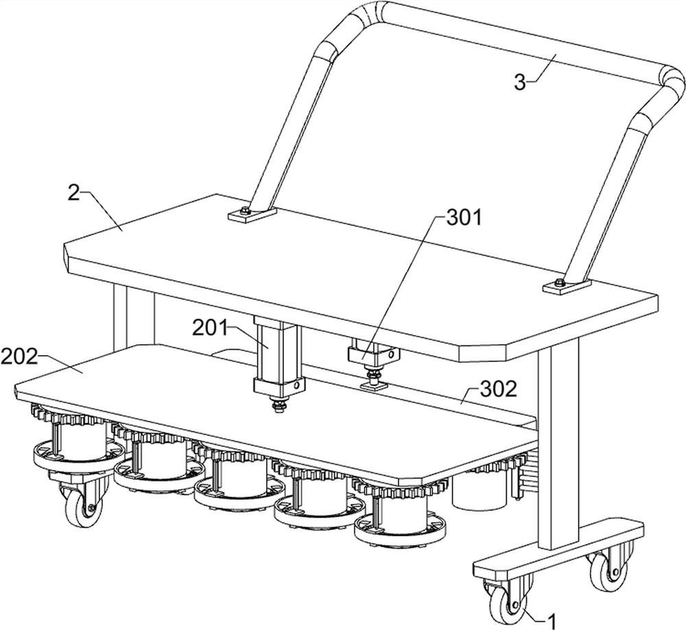
[0033] A wind cap dredging and slag collecting equipment for power station boilers, such as Figure 1-13 As shown, it includes a moving wheel 1, a bottom frame 2, a handle 3, a dredging unit and a slag cleaning unit; the top of the four moving wheels 1 is connected with a bottom frame 2; the upper right part of the bottom frame 2 is connected with a handle 3; the bottom The left part of the frame 2 is connected with a dredging unit; the middle part of the bottom frame 2 is connected with a slag cleaning unit.

[0034] The dredging unit includes a first air cylinder 201, a first installation plate 202 and a dredging mechanism 203; a first air cylinder 201 is fixedly connected to the left part of the inner and lower side of the chassis 2; the telescopic end of the first air cylinder 201 is fixedly connected to a first installation plate 202; Five dredging mechanisms 203 are fixedly connected to the lower side of the first mounting plate 202 at equal distances.

[0035] The frontm...

Embodiment 2

[0044] On the basis of Example 1, as figure 1 and Figure 14-16 As shown, it also includes a slag collection unit; the right part of the bottom frame 2 is connected with a slag collection unit; , drive shaft 405, seventh installation plate 406, third cleaning rod 407, second gear 408, eighth installation plate 409, fourth cylinder 4010, ninth installation plate 4011, collection box 4012, guide rod 4013, tenth installation The plate 4014, the eleventh mounting plate 4015 and the third rack 4016; the eighth mounting plate 409 is fixedly connected to the front side of the chassis 2; the third cylinder 401 is fixedly connected to the right part of the inner and lower side of the chassis 2; The telescopic end is fixedly connected with a sixth mounting plate 402; the lower side of the sixth mounting plate 402 is bolted with a second electric sliding rail 403; the second electric sliding rail 403 is slidably connected with a second electric sliding block 404; the second electric sli...


PUM


Abstract

The invention relates to the field of power station boilers, in particular to hood dredging and slag collecting equipment for a power station boiler. According to the technical implementation problems, a plurality of air caps are arranged on the lower surface of the boiler, large furnace slag easily slides to the air cap paths to be blocked by the air caps when the large furnace slag is raked, at the moment, large particles can be raked out only by continuously raking the large furnace slag in one or more directions, in addition, ventilation holes of the air caps in the boiler can be blocked by small-particle furnace slag, and the large-particle furnace slag cannot be raked out. Therefore, the ventilation performance is influenced to cause insufficient fuel combustion. According to the technical implementation scheme, the hood dredging and slag collecting equipment for the power station boiler comprises a bottom frame, a dredging unit and the like; a dredging unit is connected to the left of the underframe. According to the device, large furnace slag in the boiler is cleaned and the ventilation holes of the air cap are dredged, the large furnace slag can be cleaned up only by operating in one direction, the large furnace slag is prevented from being cleaned away, manual treatment is replaced, the efficiency is improved, and in addition, the ventilation holes in the air cap are dredged at the same time.

Description

technical field [0001] The invention relates to the field of power station boilers, in particular to a wind cap dredging and slag collecting equipment for power station boilers. Background technique [0002] The power station boiler is used for burning fuel for power supply. After burning, large pieces of slag will remain in the boiler. At present, the staff uses rakes to rake out the large pieces of slag. There are multiple air caps on the lower surface of the boiler. Blocks of slag are easy to slide onto the path of the hood and are blocked by the hood. At this time, it is necessary to continue raking in one or more directions to rake out the large particles. In addition, the ventilation holes of the hood in the boiler will be blocked by small particles of slag, thus Affecting ventilation performance leads to insufficient fuel combustion. At present, the staff uses a hammer to tap the metal rods aligned with the ventilation holes to dredge. There are many ventilation holes...

Claims


Application Information

Patent Timeline
Patent Type & Authority Applications(China)
IPC IPC(8): F23J1/06F23J3/00F23J3/06
CPCF23J1/06F23J3/00F23J3/06
Inventor 郑建
Owner 郑建
Why Eureka
Try Eureka