
Welding correction method, welding correction equipment and readable storage medium

A correction method and welding information technology, applied in design optimization/simulation, instrumentation, electrical digital data processing, etc., can solve problems such as unstable tension, weak bonding strength, and falling off, so as to improve welding stability, enhance welding strength, Eliminates the effect of false welding

Pending Publication Date: 2022-07-01
SHENZHENSHI YUZHAN PRECISION TECH CO LTD
View PDF0 Cites 0 Cited by
  • Summary
  • Abstract
  • Description
  • Claims
  • Application Information

AI Technical Summary

Problems solved by technology

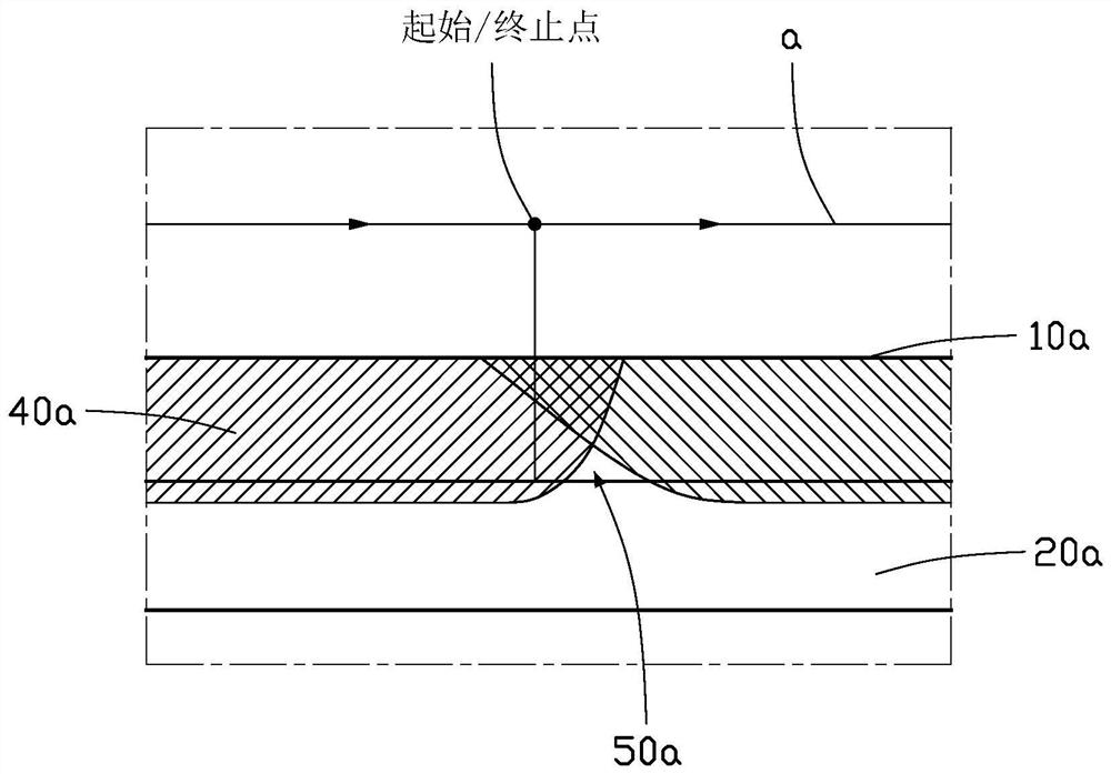
Usually, since the welding path of each welding point is circular, the starting point of welding coincides with the end point, but in the welding process, the light output power required for welding to form a penetration depth 40a between the first metal piece 10a and the second metal plate 20a reaches preset power, and it takes a certain amount of time for the light output power to reach the preset power, and at the starting point of welding, part of the light output energy is absorbed by the first metal piece 10a in the cooling state, resulting in the virtual welding area 50a often appearing in the initial stage of welding, The penetration depth 40a under the multiple welding spots 30a has a virtual welding area 50a, which leads to weak bonding strength between the first metal piece 10a and the second metal plate 20a, and the pulling force is unstable, and it is easy to fall off during the impact process

Method used


Image

  • Welding correction method, welding correction equipment and readable storage medium
  • Welding correction method, welding correction equipment and readable storage medium
  • Welding correction method, welding correction equipment and readable storage medium

Examples


Embodiment Construction

[0059] In order to more clearly understand the above objects, features and advantages of the present application, the present application will be described in detail below with reference to the accompanying drawings and specific embodiments. It should be noted that the embodiments of the present application and the features in the embodiments may be combined with each other in the case of no conflict.

[0060] In the following description, many specific details are set forth to facilitate a full understanding of the present application, and the described embodiments are only a part of the embodiments of the present application, but not all of the embodiments. Based on the embodiments in the present application, all other embodiments obtained by those of ordinary skill in the art without creative efforts shall fall within the protection scope of the present application.

[0061]In the description of this application, it should be understood that the terms "center", "longitudina...


PUM


Abstract

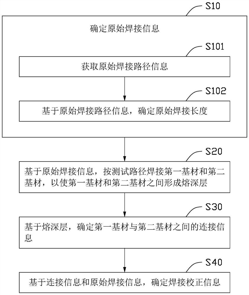
The invention provides a welding correction method and device and a computer readable storage medium, and the welding correction method comprises the steps that original welding information is determined; based on the original welding information, a first base material and a second base material are welded according to a test path, so that a fusion depth layer is formed between the first base material and the second base material; determining connection information between the first base material and the second base material based on the fusion depth layer; based on the connection information and the original welding information, welding correction information is determined, a test welding path is determined through the original welding information, a first base material and a second base material are welded according to the test welding path to form a fusion depth layer, connection information between the first base material and the second base material is obtained according to the fusion depth layer, and the connection information between the first base material and the second base material is obtained. And acquiring welding correction information according to the connection information and the original welding information, and correcting the original welding path by using the welding correction information to eliminate virtual welding between the first base material and the second base material so as to enhance the welding strength between the first base material and the second base material.

Description

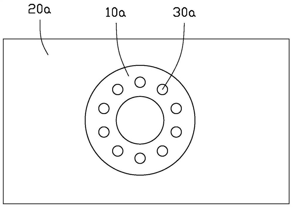
technical field [0001] The present application relates to the technical field of welding, and in particular, to a welding calibration method, a welding calibration device and a readable storage medium. Background technique [0002] As shown in Fig. 1(A) and Fig. 1(B), Fig. 1(A) is a top view of a workpiece in the prior art after welding, and Fig. 1(B) is a section based on a welding spot in Fig. 1(A) Sectional view of the workpiece. The first metal piece 10a is fixedly connected to the second metal piece 20a to form a workpiece including welding. Generally, the operation process of welding the first metal piece 10a to the second metal plate 20a is as follows: the laser goes to the first metal piece 20a in a circular welding path. A metal piece 10a emits a laser, the laser fuses the first metal piece 10a and the second metal plate 20a to form a penetration 40a, and a welding spot 30a is formed on the surface of the first metal piece 10a to realize the connection. Generally,...

Claims


Application Information

Patent Timeline
IPC IPC(8): G06F30/20G06F119/02
CPCG06F30/20G06F2119/02
Inventor 刘奥运何楚星
Owner SHENZHENSHI YUZHAN PRECISION TECH CO LTD
Learn More