Golf club head and manufacturing method for the same

Inactive Publication Date: 2013-04-25
BRIDGESTONE SPORTS
View PDF4 Cites 6 Cited by
  • Summary
  • Abstract
  • Description
  • Claims
  • Application Information

AI Technical Summary

Benefits of technology

The patent text is addressing how to reduce the weight of golf club heads while maintaining strength. One method is to reduce the thickness of different parts of the golf club head, such as the sole, side, and crown. However, this can lead to shrinkage of welds, which can lower the strength of certain parts of the golf club. The patent text looks to solve this problem to ensure the golf club remains strong and durable.

Problems solved by technology

If the thickness is small, shrinkage of welds in the sole part, crown part, and face part that are welded together can lower strength of joint portions between the sole part, the crown part, and the face part.
When a ball is hit with the large size golf club head, if the thickness of the sole part or the crown part is less than sufficient, a hitting sound becomes dead, so that even when the ball is hit well, a player and people nearby might misidentify that he or she missed a shot.

Method used


Image

  • Golf club head and manufacturing method for the same
  • Golf club head and manufacturing method for the same
  • Golf club head and manufacturing method for the same

Examples


first embodiment

[0050]Hereinafter, a golf club head according to the present invention will be described with reference to FIGS. 1 to 7.

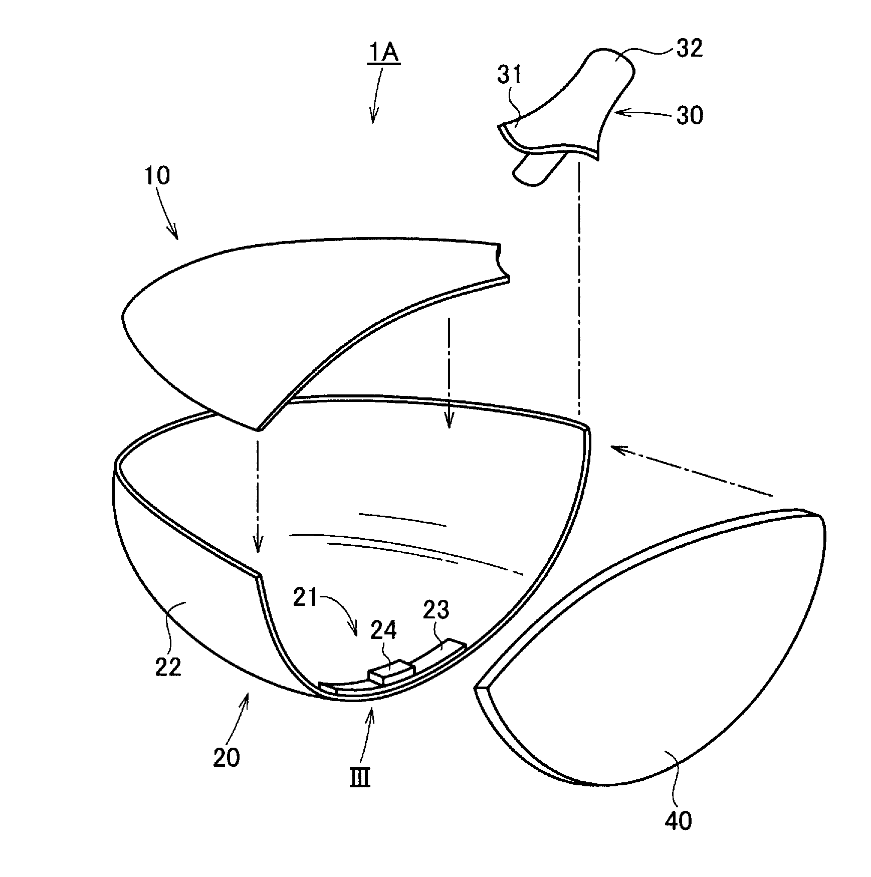
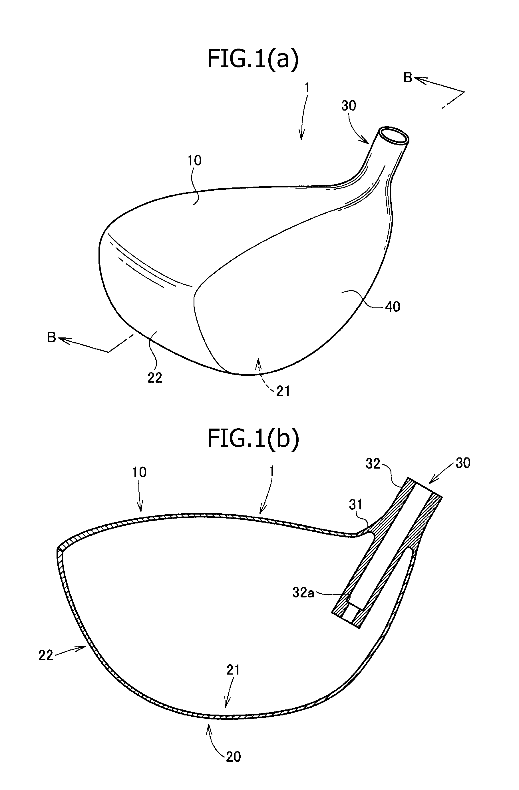
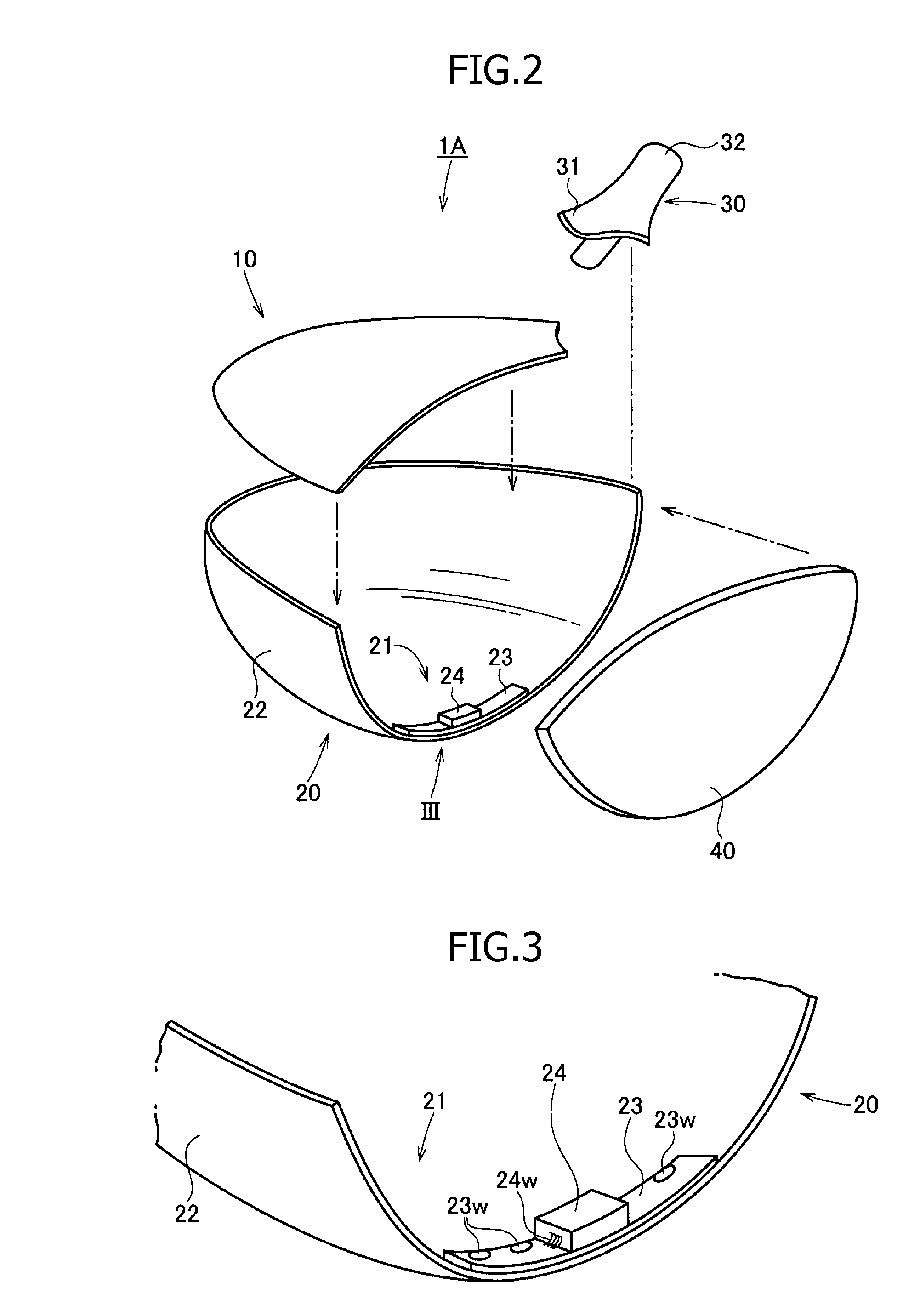
[0051]As shown in FIG. 1, this golf club head 1 includes a crown part 10, a lower part 20, a hosel part 30, and a face part 40, which are integrated with each other by welding. As shown in FIG. 2, the lower part 20 includes a sole part 21 and a side part 22 rising from the sole part 21. The side part 22 extends from a toe side to a heel side via a back side.

[0052]The hosel part 30 includes a substantially bell-shaped skirt part 31 and a column 32 projecting upward and downward from the skirt part 31. As shown in FIG. 1B, a stepped part 32a having a small diameter is provided near a bottom end of the inner surface of the column 32. A shaft (not shown) is inserted into the hosel part 30 until an end thereof butts this stepped part 32a and is fixed with adhesive. Although, according to this embodiment, the hosel part 30 is so provided that a bottom end of the column 3...

second embodiment

[0069]Hereinafter, another golf club head and a manufacturing method for the same will be described with reference to FIGS. 11 to 18.

[0070]As shown in FIG. 11, this golf club head 1 includes a crown part 10, a lower part 20, a hosel part 30 and a face part 40, which are integrated with each other by welding. As shown in FIG. 12, the lower part 20 includes a sole part 21 and a side part 22 rising from the sole part 21. The side part 22 extends from the toe side to the heel side through the back side.

[0071]The hosel part 30 includes a substantially bell-shaped skirt part 31 and a column 32 projecting upward and downward from the skirt part 31. As shown in FIG. 11B, a stepped part 32a having a small diameter is provided near a bottom end of the inner surface of the column 32. A shaft (not shown) is inserted into the hosel part 30 until an end thereof butts this stepped part 32a and is fixed with adhesive. Although, according to this embodiment, the hosel part 30 is provided so that a ...


PUM

PropertyMeasurementUnit
Lengthaaaaaaaaaa
Lengthaaaaaaaaaa
Lengthaaaaaaaaaa

Abstract

A golf club head manufacturing method, including: welding a first reinforcing piece with first thickness to a central portion between a toe and a heel, so as to extend along an edge of a face side of a sole part, the sole part being part of a lower part formed integrally with a side part; welding a second reinforcing piece of second, larger thickness to a central portion between the toe and heel so as to extend along the edge on the face side of the first piece; welding a face part to the first and second pieces from an inner space of the lower part; welding a hosel part to the lower and face parts; welding a crown part to the lower, face and hosel parts; and welding the lower and face parts together from the outside.

Description

CROSS-REFERENCE TO RELATED APPLICATIONS[0001]The present invention relates to Japanese Patent Application No. 2010-226731 and Japanese Patent Application No. 2010-226732, filed on Oct. 6, 2010, by Hideo Shimazaki, an inventor.BACKGROUND OF THE INVENTION[0002]The present invention relates to a golf club head having a hollow structure and made of a metal and a manufacturing method for the same, more particularly to a wood type or similar type golf club head and a manufacturing method for the same.[0003]As the wood type golf club head represented by a driver and a fairway wood, the club heads having a hollow structure and made of a metal have been widely used. Generally, the wood type golf club head having the hollow structure includes a face part for hitting a ball, a crown part constituting an upper face part of the golf club head, a sole part constituting a bottom face part of the golf club head, a side part constituting side face parts on a toe side, a back side and a heel side of ...

Claims


Application Information

Patent Timeline
IPC IPC(8): A63B53/04B23K31/02
CPCA63B2053/0454A63B2059/0003A63B53/0466A63B2053/0408B23K31/02B23K9/0026A63B2053/0437B23K11/0033B23K11/115B23K33/004B23K2203/14A63B2053/0416B23K9/167A63B60/00A63B53/0408A63B53/0416A63B53/0437A63B53/0454A63B60/002B23K2103/14
Inventor SHIMAZAKI, HIDEO
Owner BRIDGESTONE SPORTS
Why Eureka
Try Eureka